6" F/6 Newtonian Reflector Telescope - CURIOSITY

Chapter 00 // INTRODUCTION, the Why? Where? How?
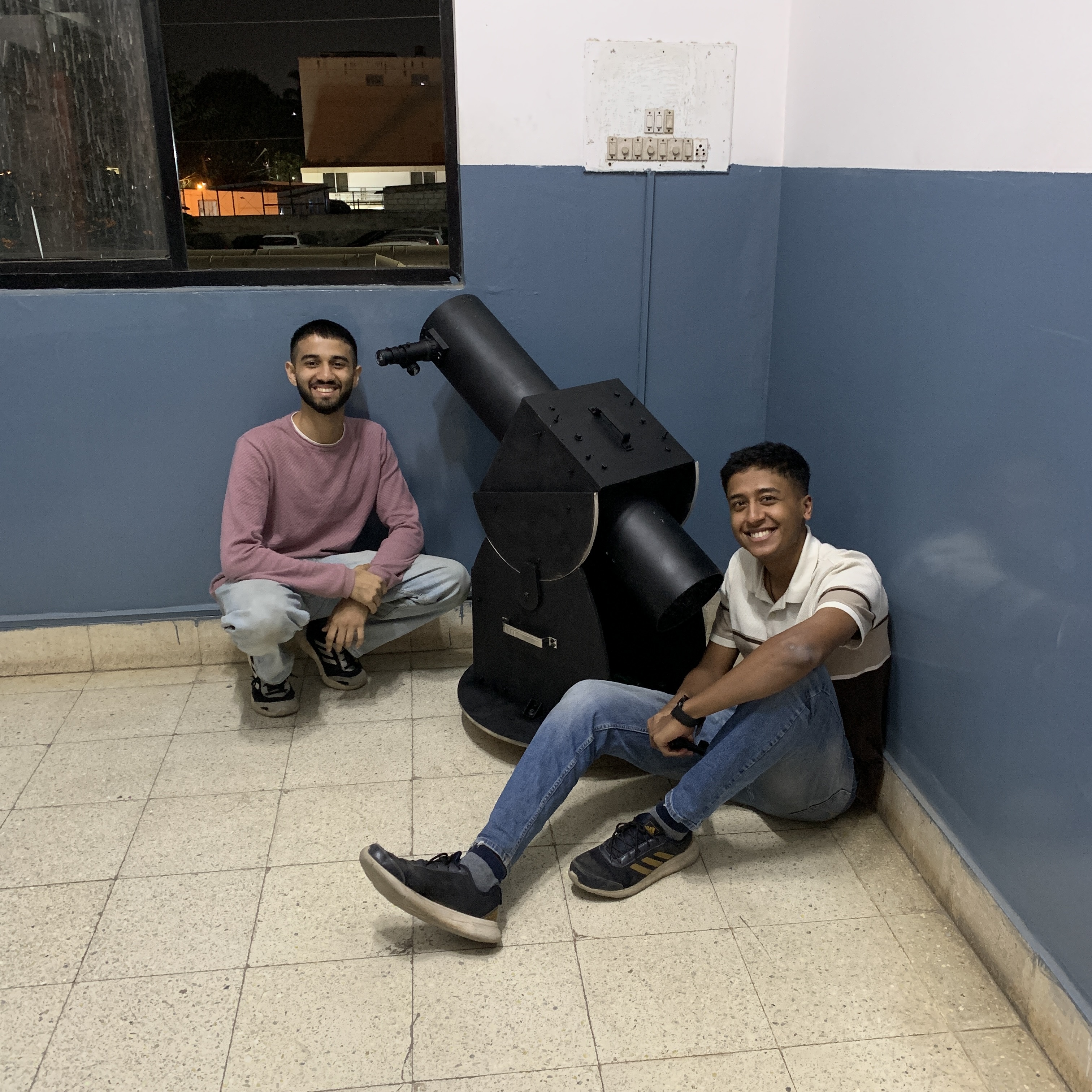
Madhav on Computer M & Swarup on Computer S.
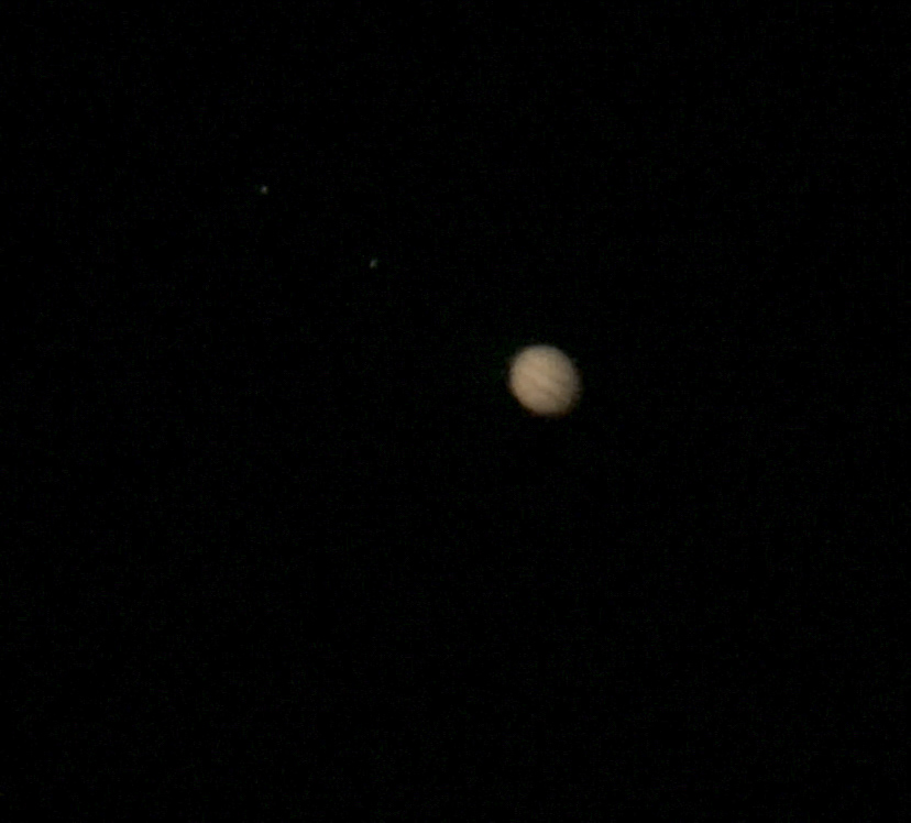
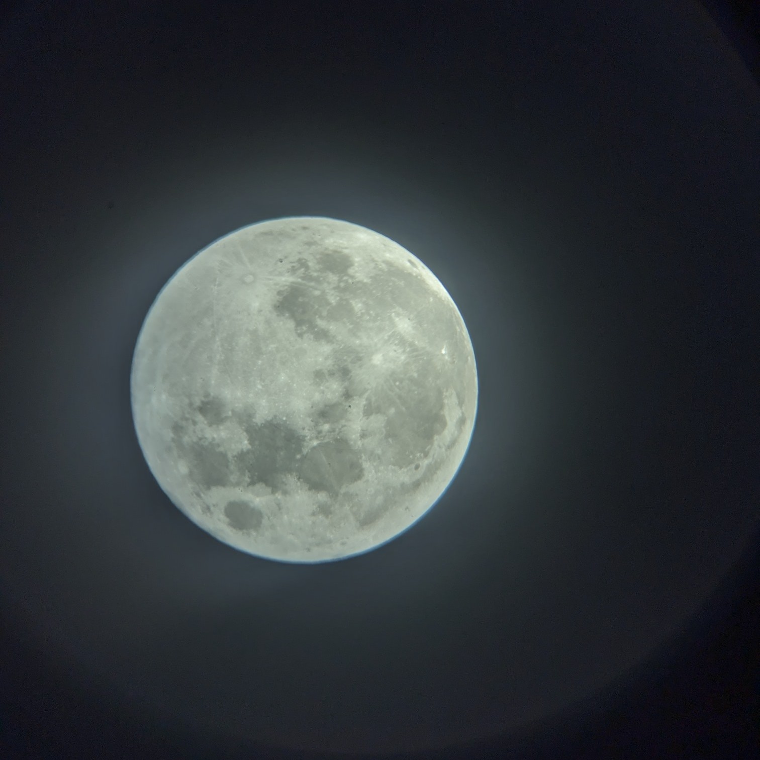
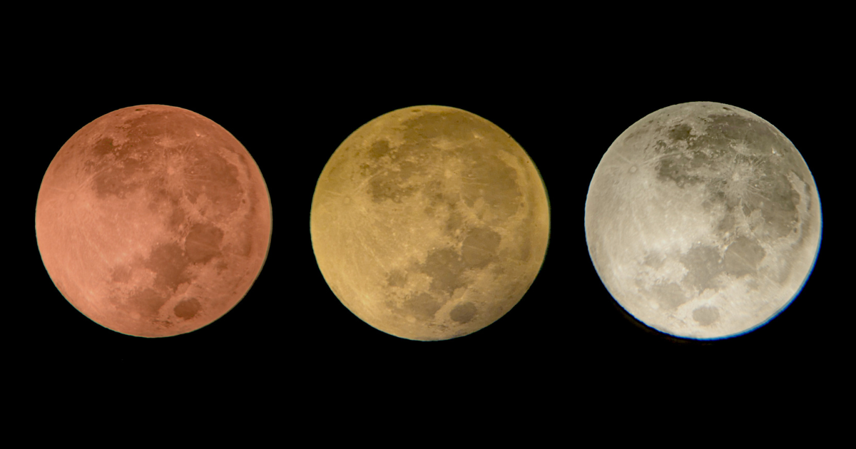
Both, looking at their reddit feeds and getting awed by the pictures of Moon, Jupiter, Saturn, Orion Nebulae and what not, clicked by people all around the world.
Us discussing, HOW MUCH DOES A DECENT TELESCOPE COST?
Well, it does cost a lot (*a lot is definitely subjective). Living in bengaluru, India where the current period of months(October to March) aids us to stargaze with the most beautiful clear skies. Something had to be done, so we jumped on searching our reddit feeds and cloudy nights to get an understanding on what people have accomplisheed, I came across this book called “Build Your Own Telescope by Richard Berry (1985)”, which communicated in a very interesting way. The initial thought following the book was to build a 4" telescope but eventually we jumped onto a 6" Newtonian Reflector with Dobsonian Mount.
Hence, the name of our telescope "CURIOSITY".
Chapter 01-A // Dimensions & Calculations
The image shown below is the most essential and the easiest calculation that one has to look for while building a newtonian reflector telescope.
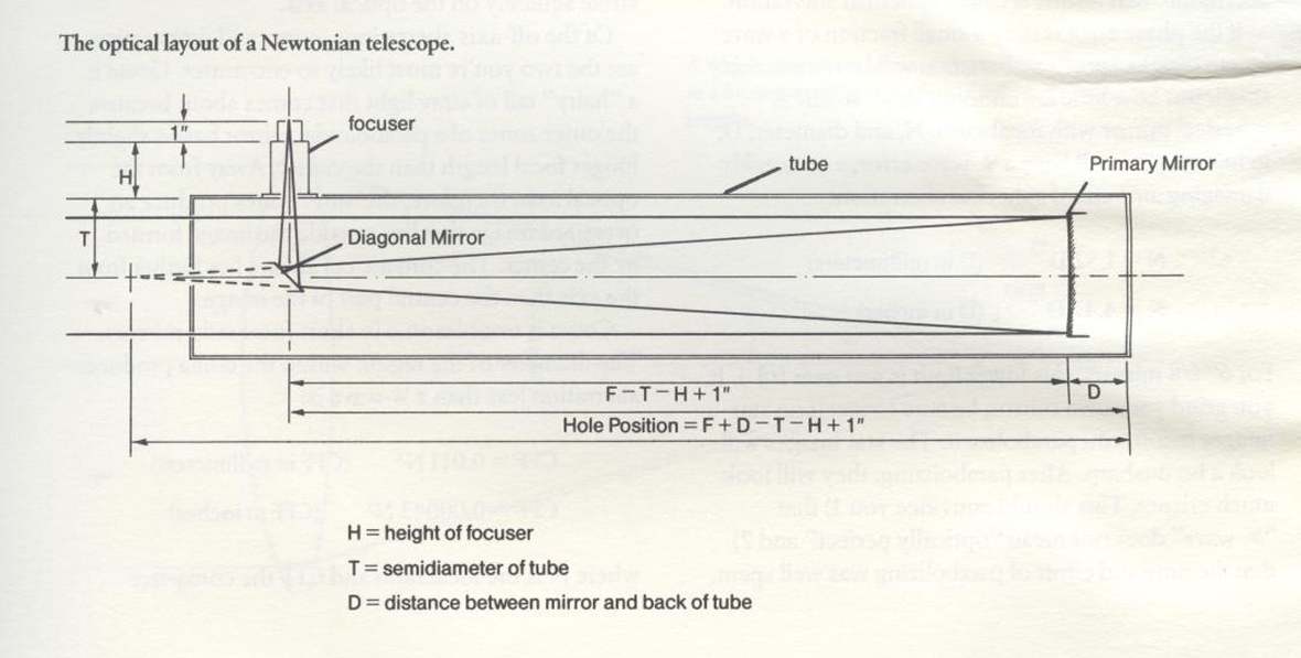
Ref: How to build your own telescope by Richard berry
In our case, for the distance between the diagonal mirror and the primary mirror, we did not strictly adhere to the +1", rather we subtracted it i.e., our final equation looked like F-T-H-1". This was done because of the focuser size. The calculation looks like
- F = Focal Length = 900mm
- T = Tube inner dia = 95mm
- H = Height of focuser = 96mm
- So, F-T-H-25 = 900 - 95 - 96 - 25 = 684mm
Q. Why did we go for a 190mm inner diameter of tube?
A. After referring a lot of sources over the internet and also during the assembly process of the telescope, it is advised to maintain an offset of ≥ 20mm from the size of primary mirror i.e., for a 6" or 150mm primary mirror size, 150 + (2*20) = 190mm should be the minimum inner diameter of your PVC tube.
- PVC Tube dimension: Ø190mm as inner diameter and Ø200mm as outer diameter with a length of 1000mm.
- 6" Newtonian Telescope kit purchased from Tejraj and co. who provide a 6" primary mirror, 25mm eyepiece, a diagonal mirror as was mentioned in the previous chapter and finally a Rack-n-pinion focuser.
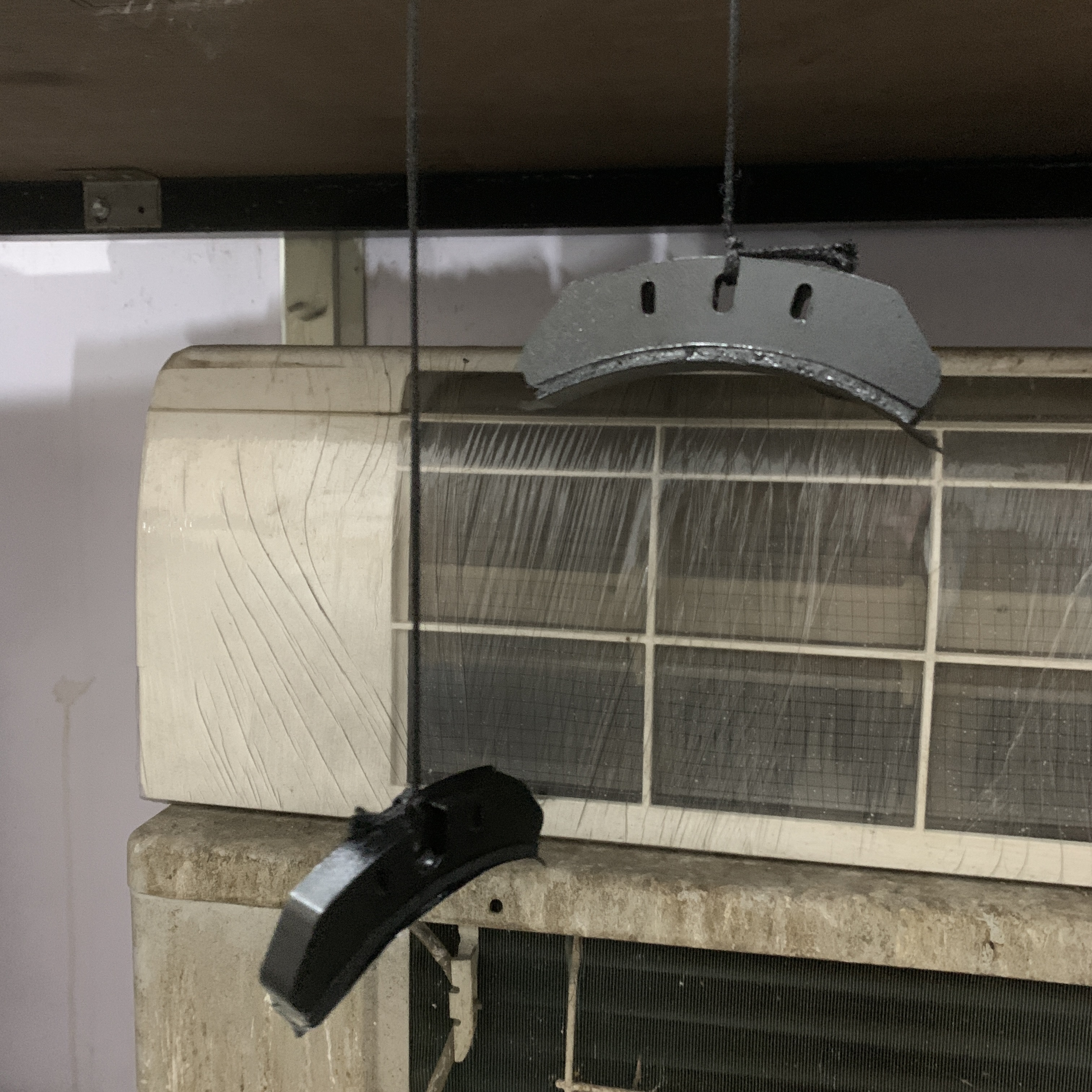
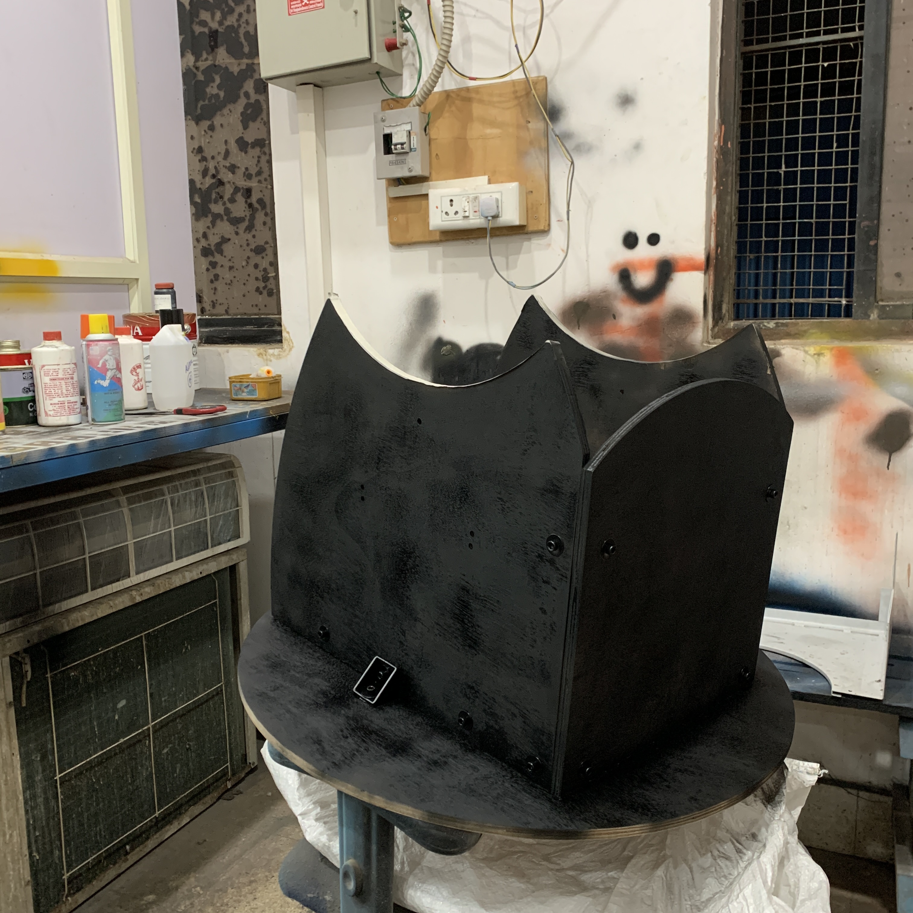
- Matte Black Spray paints which we got it from a nearby hardware store.
Chapter 01-B // CAD Modelling & Designing
The following images are snippets of our design from Fusion 360 software which supports student licences, though some limitations, but does fulfill our job.
Use the cursor to move it around and scroll to zoom in and zoom out.
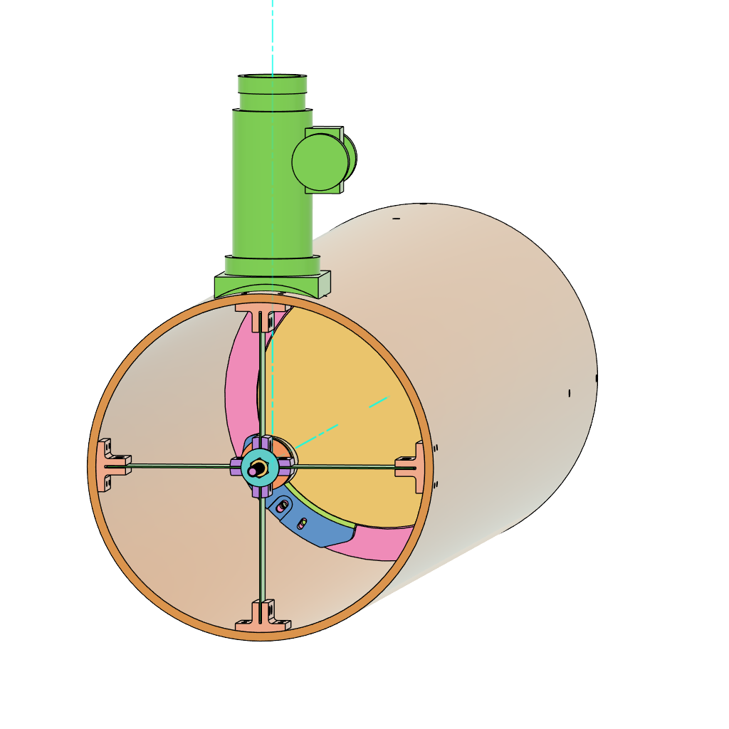
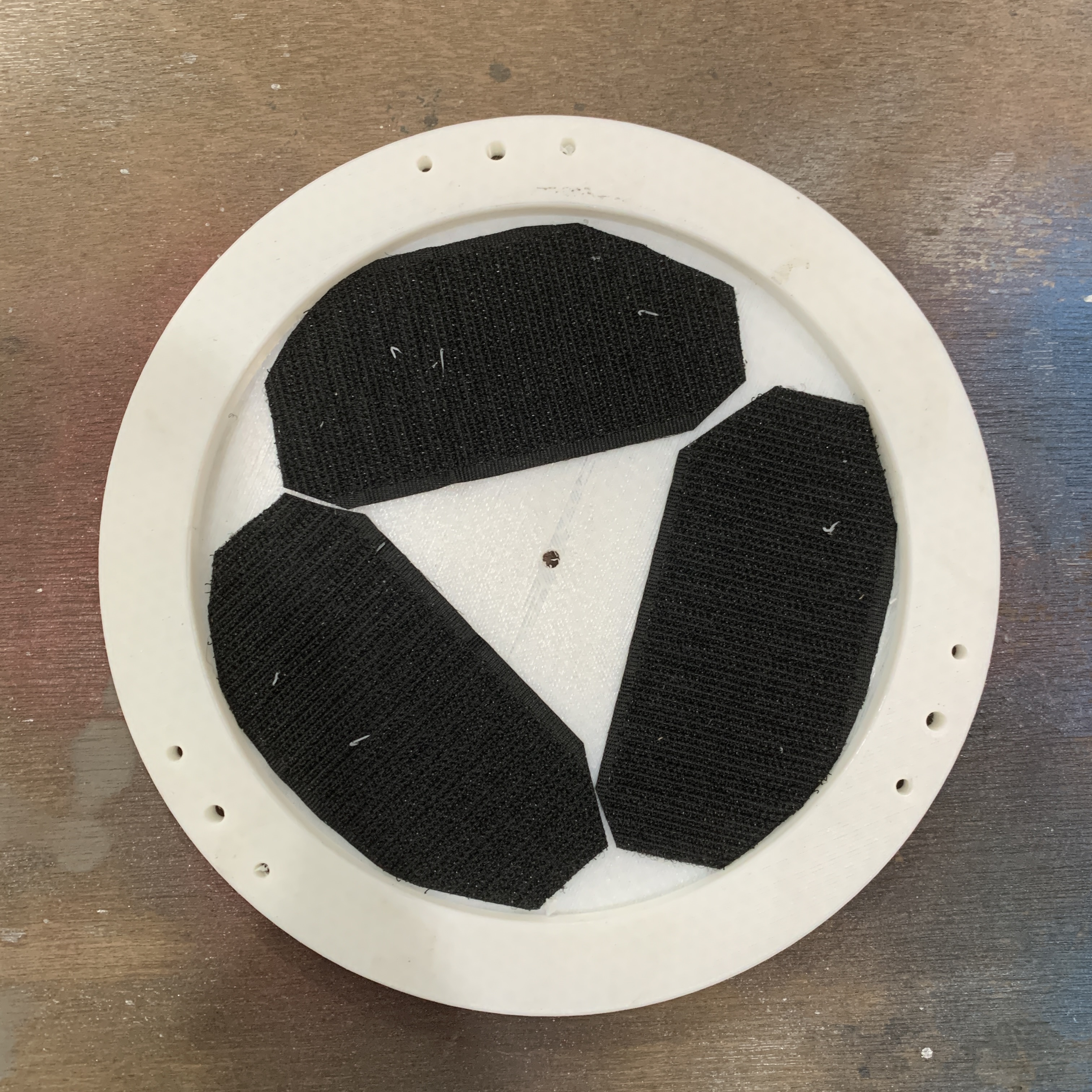
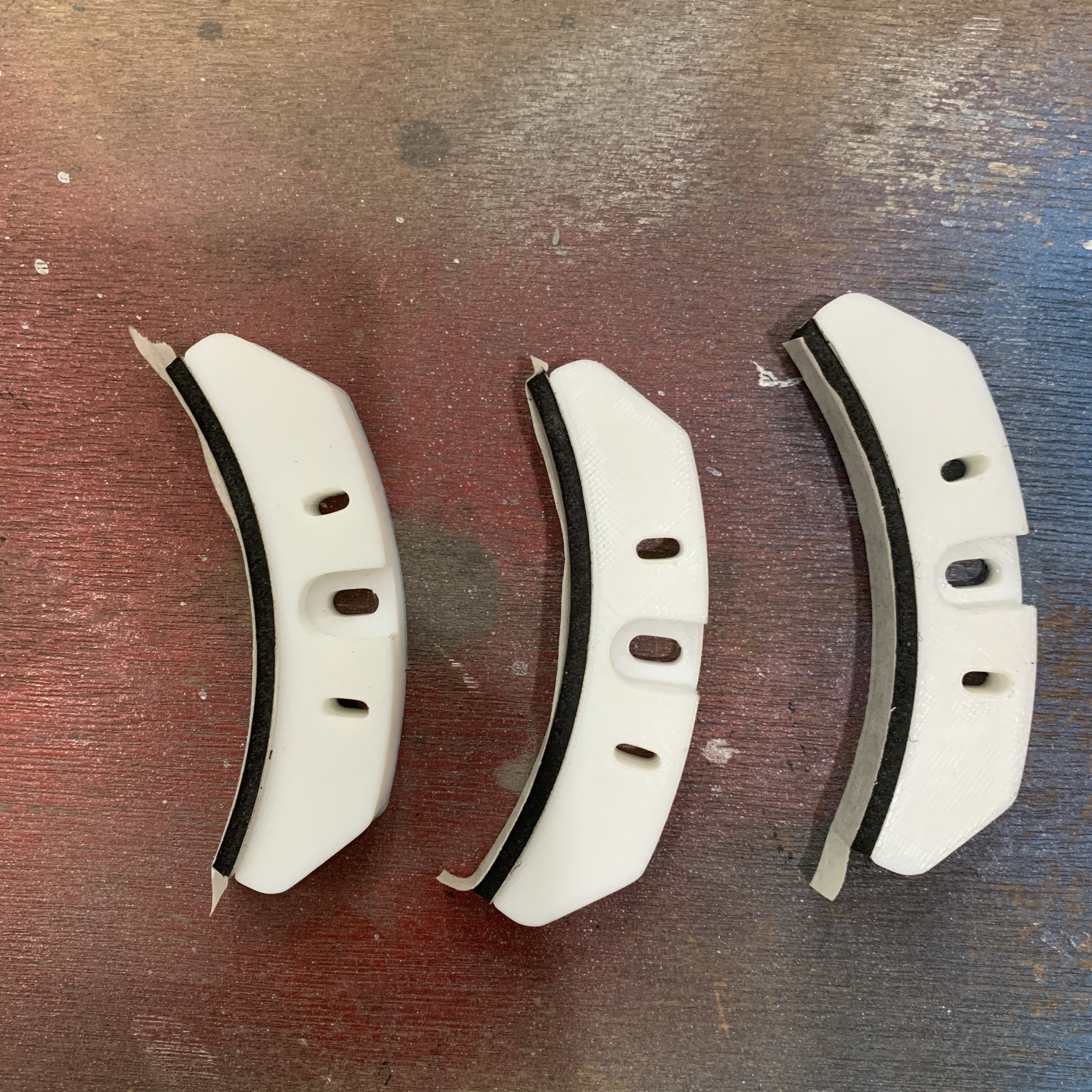
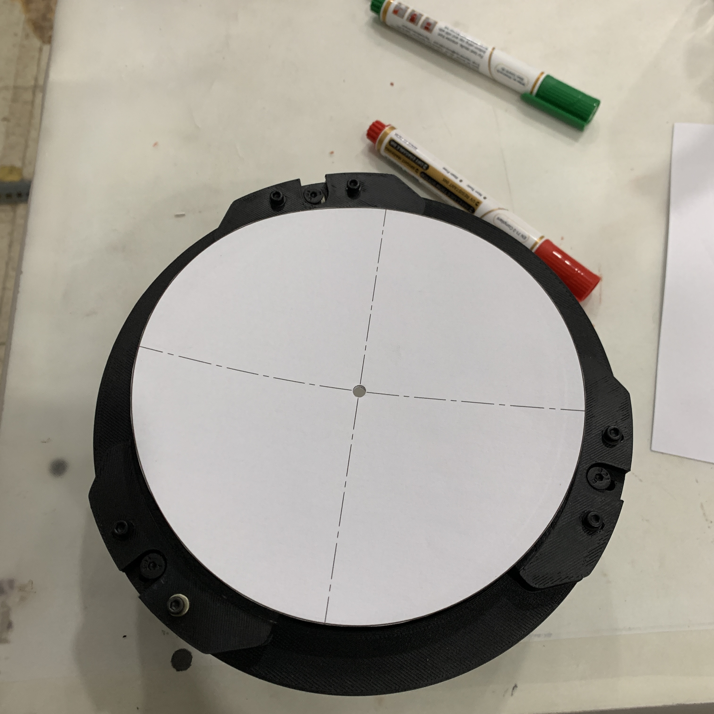
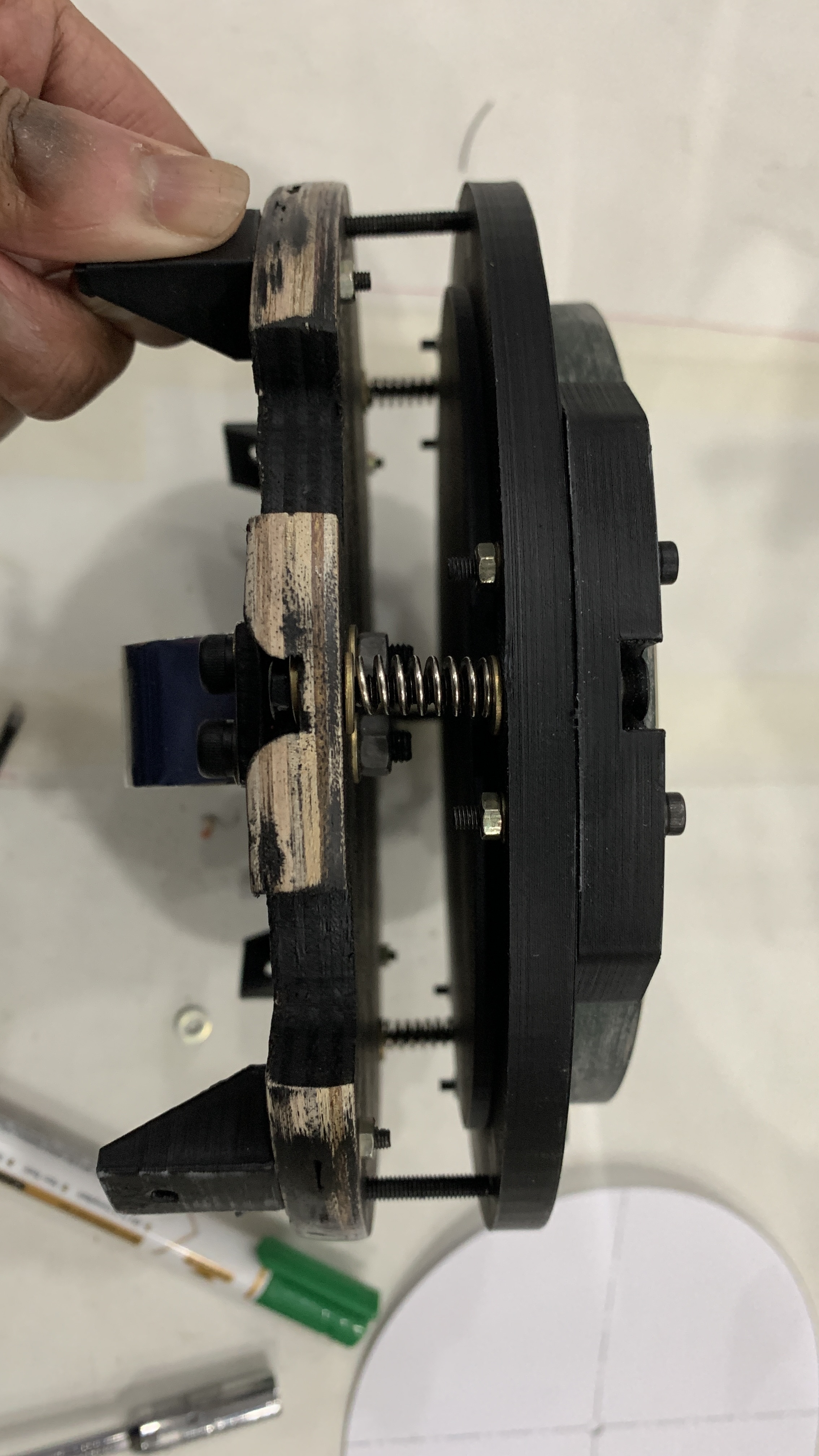
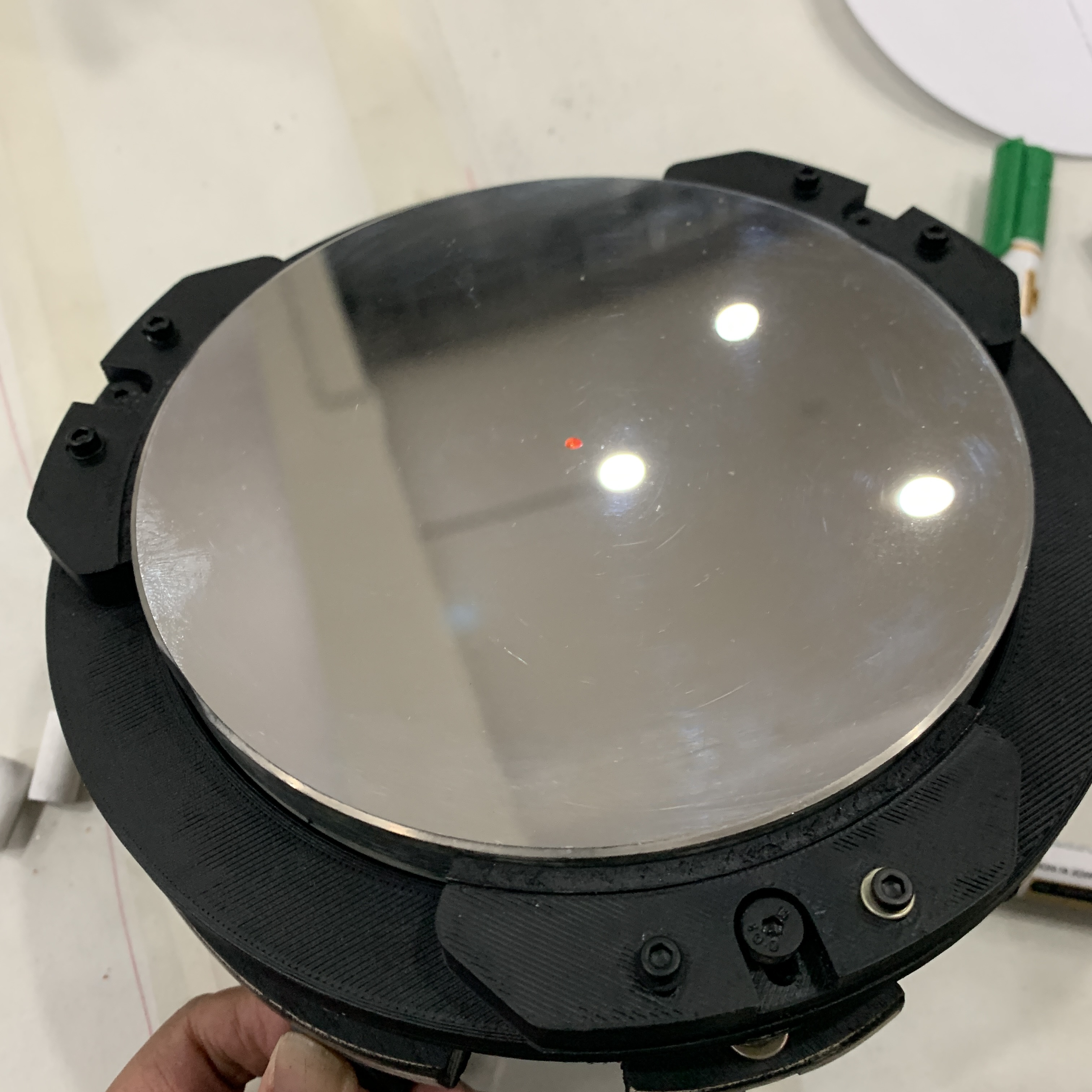
>> 01_PRIMARY MIRROR ASSEMBLY
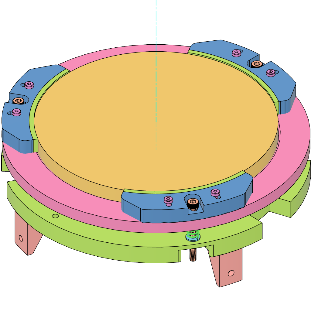
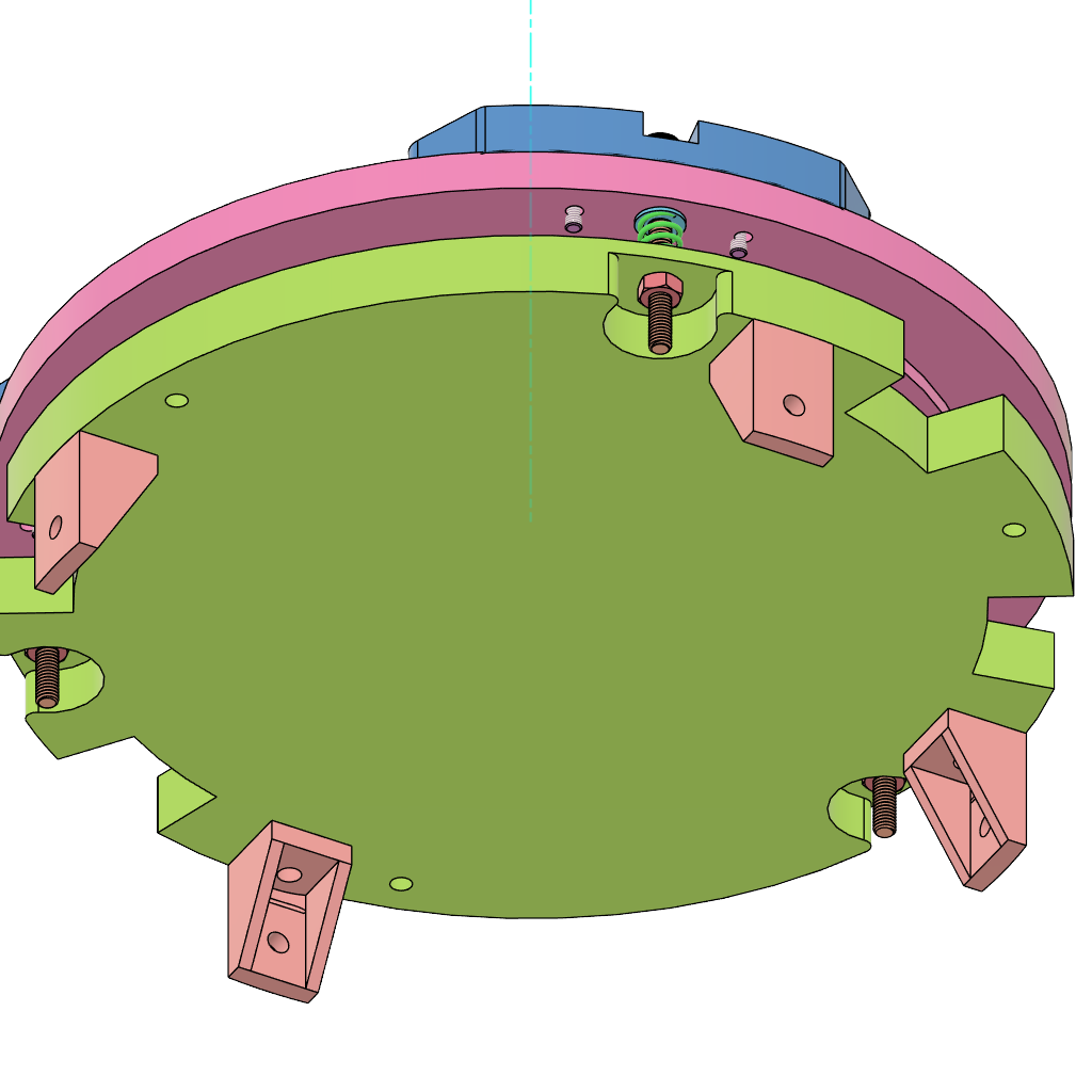
Based on the images represented above:
- Back of the mirror is adhered with adhesive velcro hook and the pink component (housing) is adhered with velcro loop.
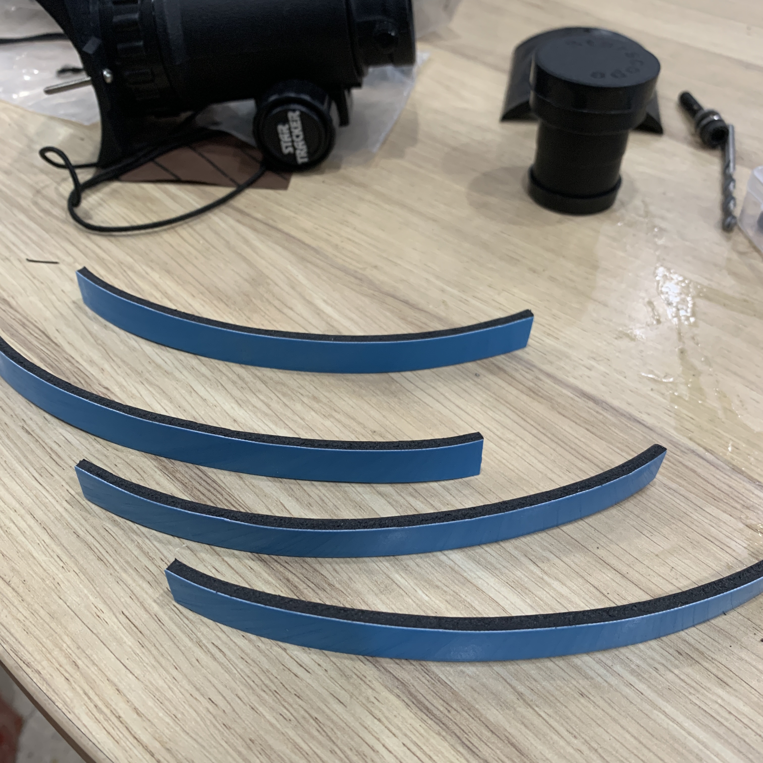
- The face of the blue components in contact with the mirror is adhered with a 2mm thick rubber padding to hold the mirror in position.
- Excluding the green component which is plywood, all the other components are 3D printed.
- CAD Link: GRABCAD - Curiosity
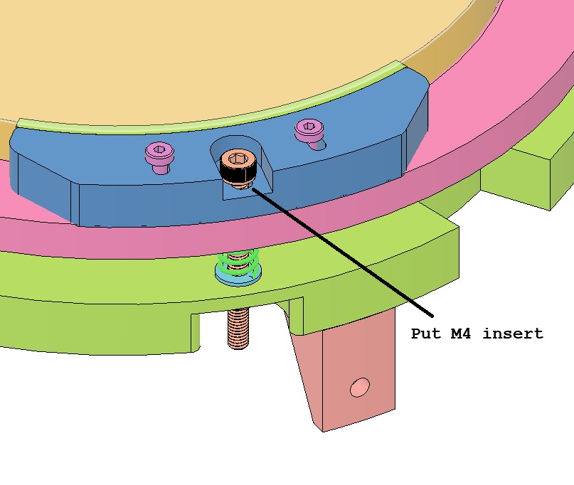
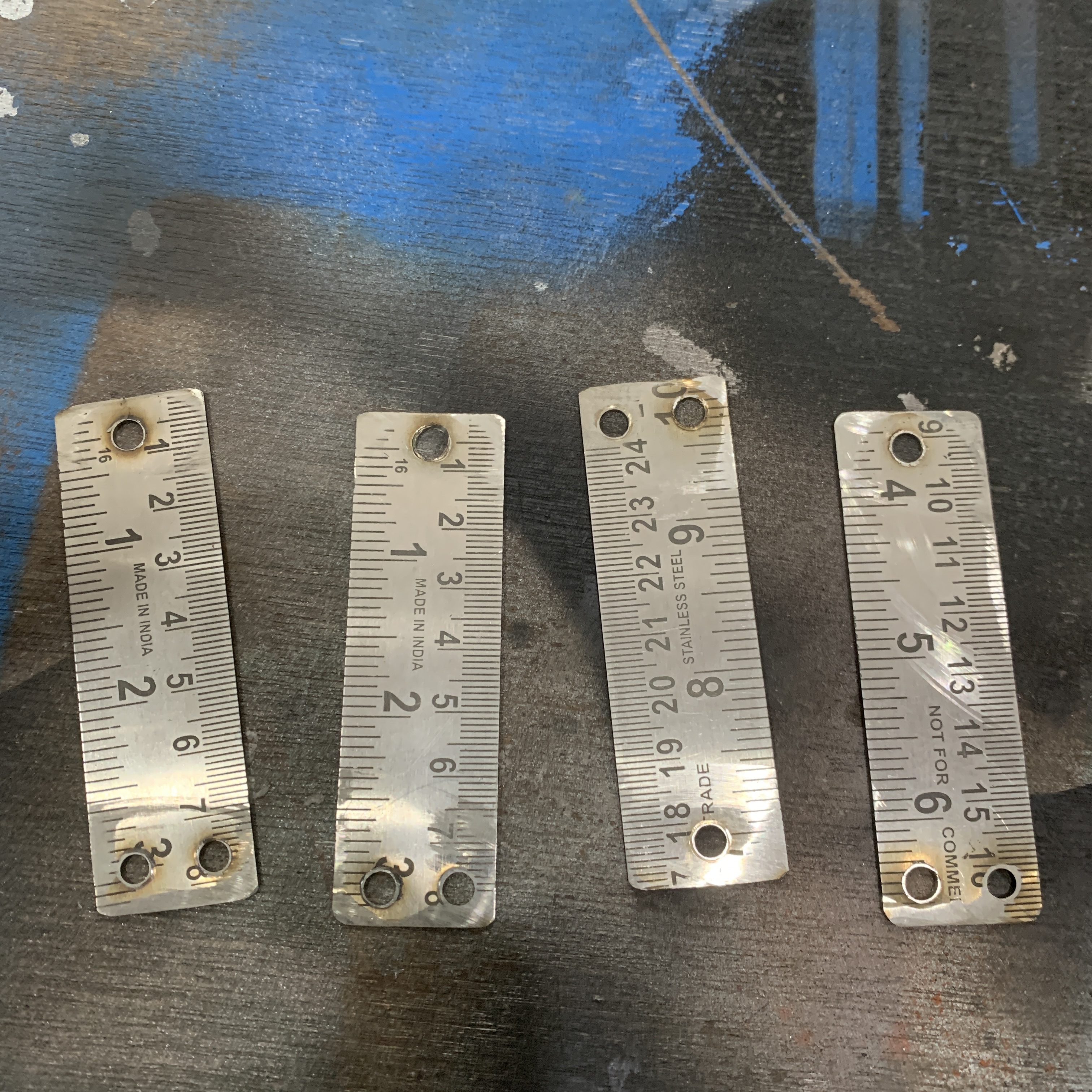
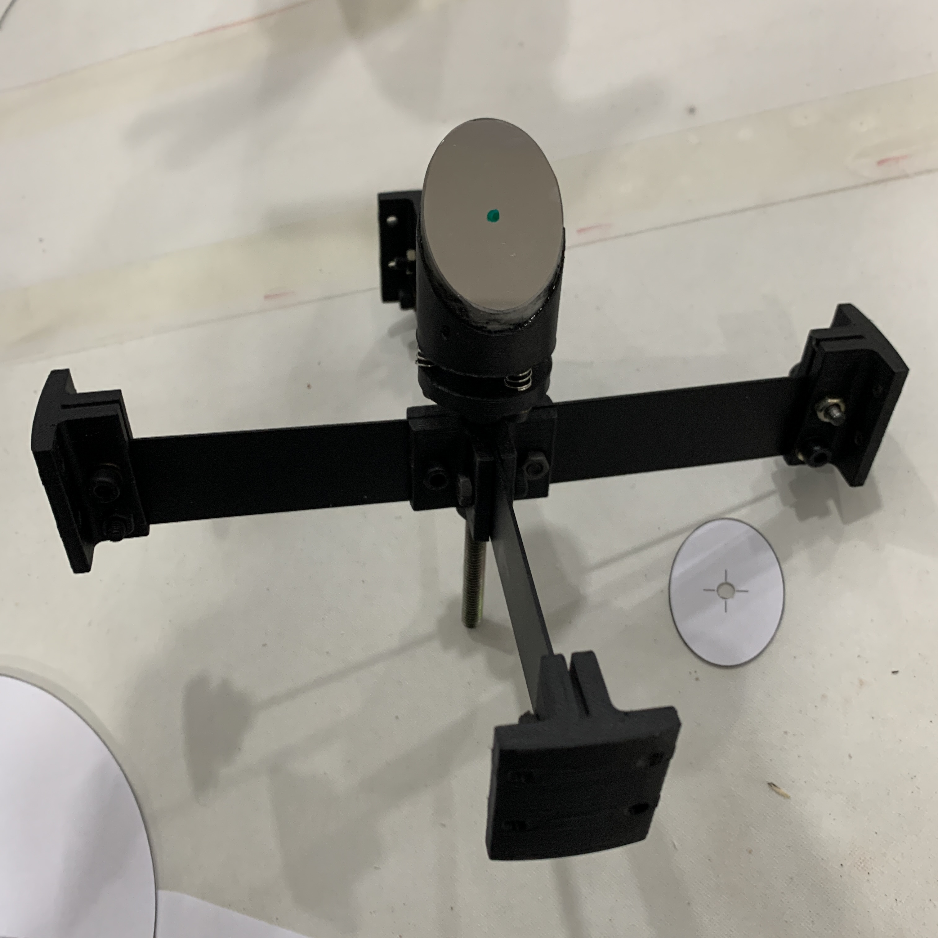
>> 02_SECONDARY MIRROR with SPIDER VANE ASSEMBLY
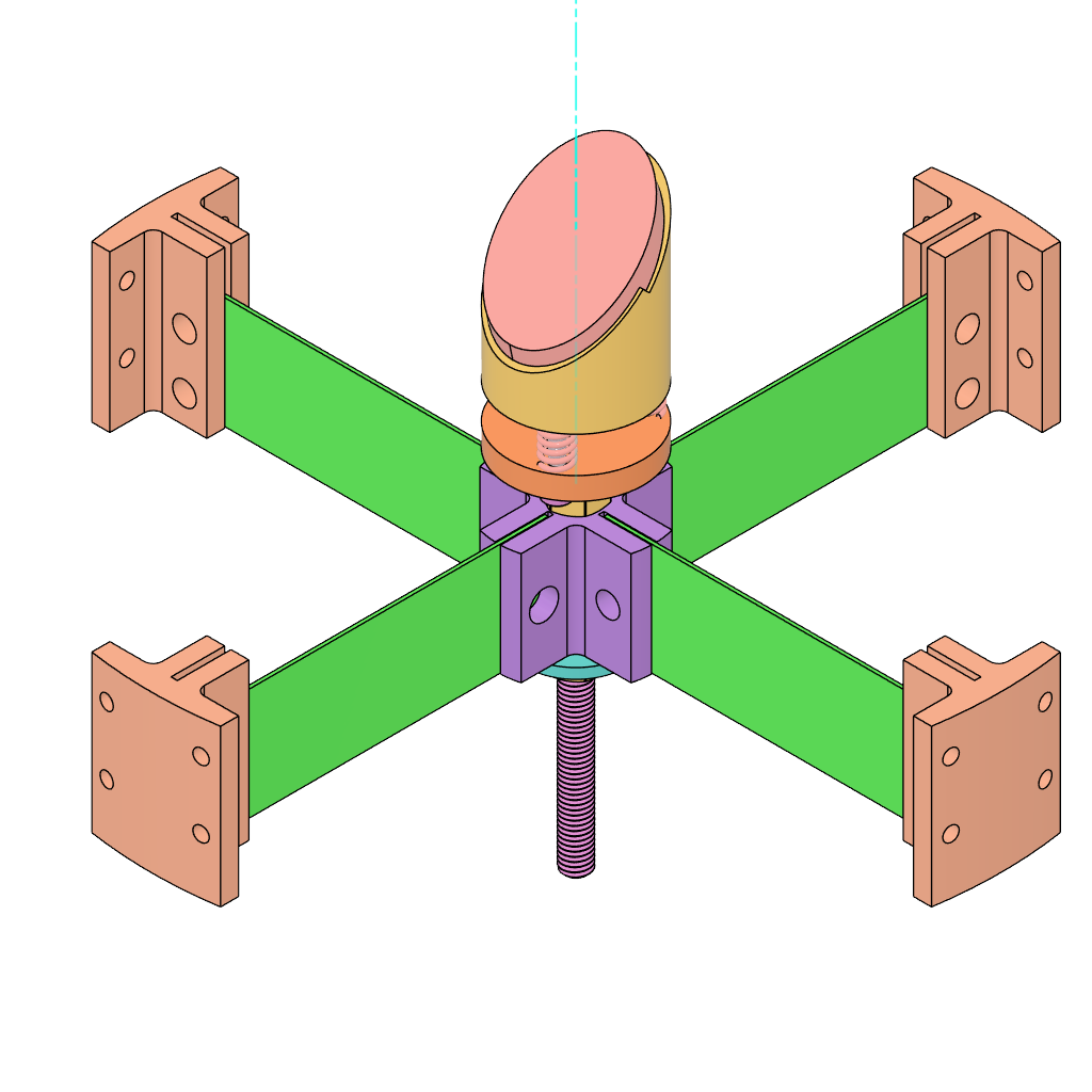
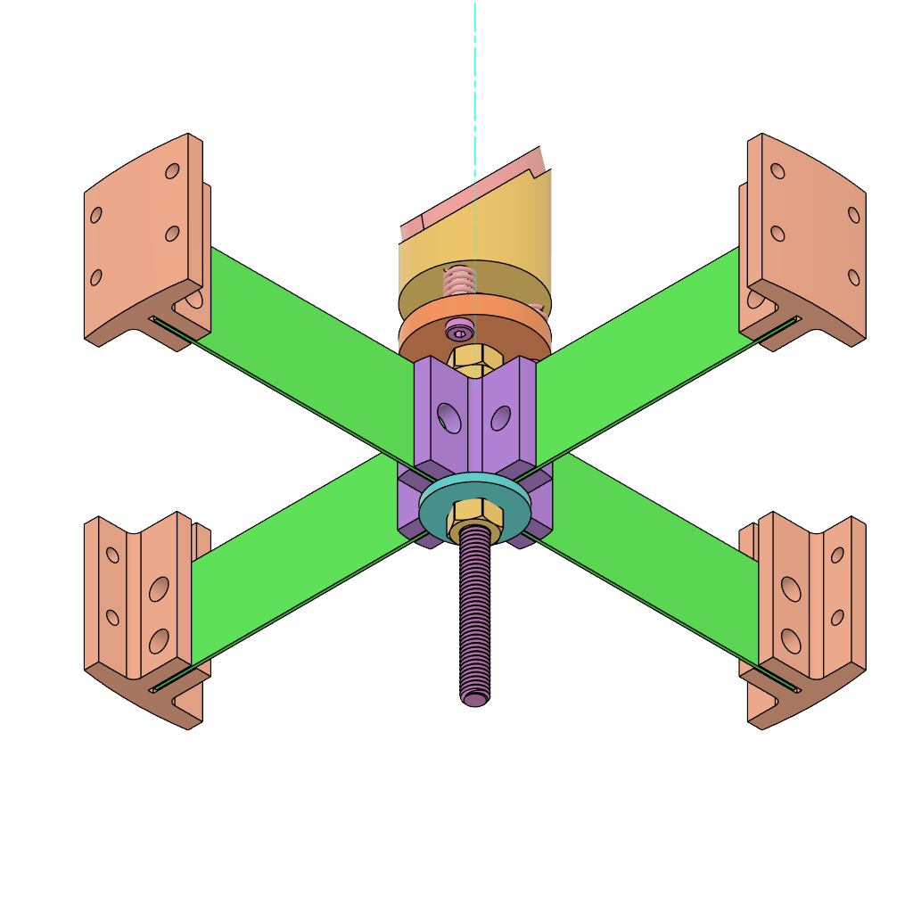
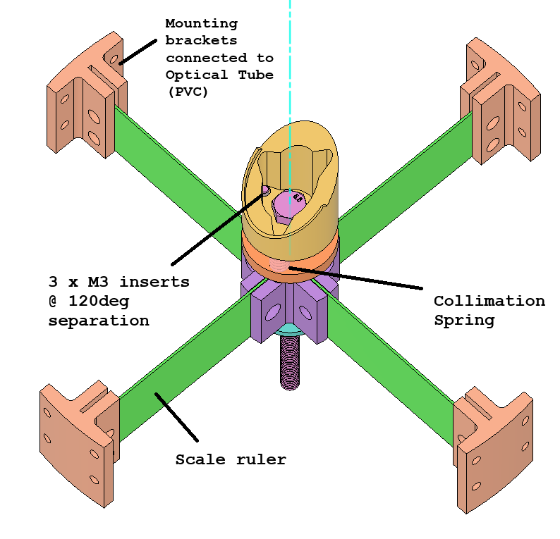
Based on the images represented above:
- The green component represents COTS (commercially off the shelf) 0.7mm thick scale/ruler of 30cm length which we got from a stationary store. For spider vane designs, follow the below links for better understanding. To take a note of "Diffraction Spikes"
- >> Some thoughts about spiders in Newtonian telescopes by Nils Olof Carlin
- >> Cloudy Nights: Spider and Secondary Diffraction: what to do, what to avoid
- >> Findlight blog: Diffraction Spikes from Telescope Secondary Mirror Spiders
- The secondary mirror is adhered to the top yellow bracket (groove supported for ease of positioning) using standard strong adhesive. To ensure wearing gloves while handling the mirrors.
- Make sure to clean the mirrors using a standard alcohol based wipes.
- CAD Link: GRABCAD - Curiosity
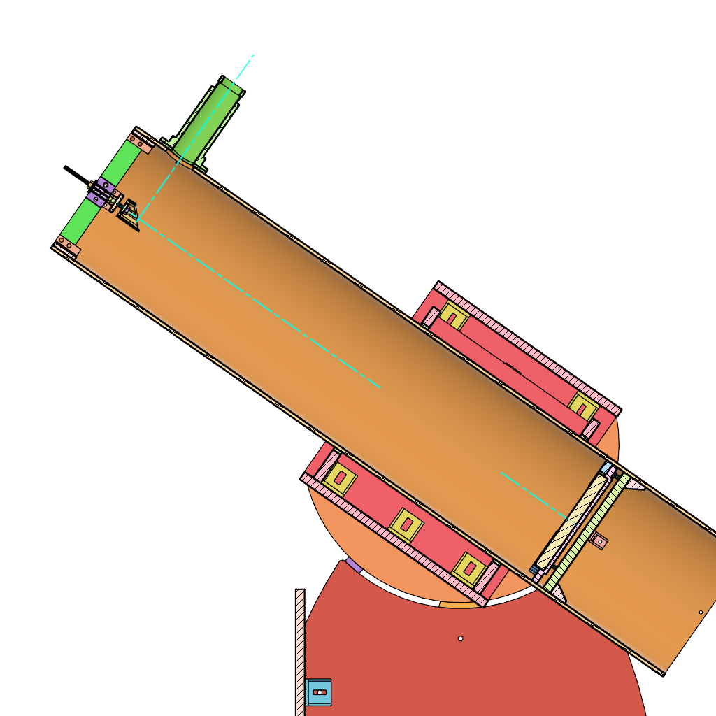
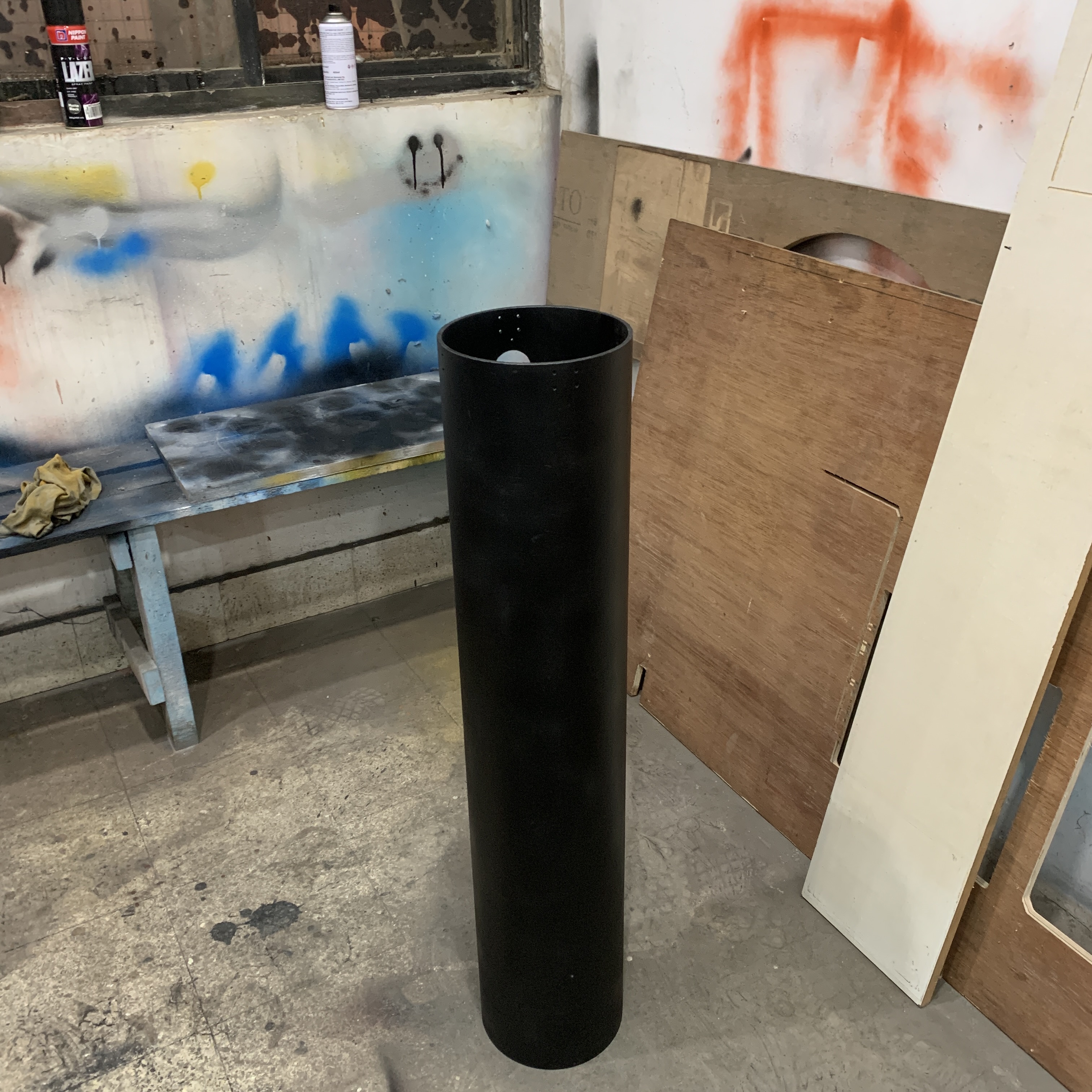
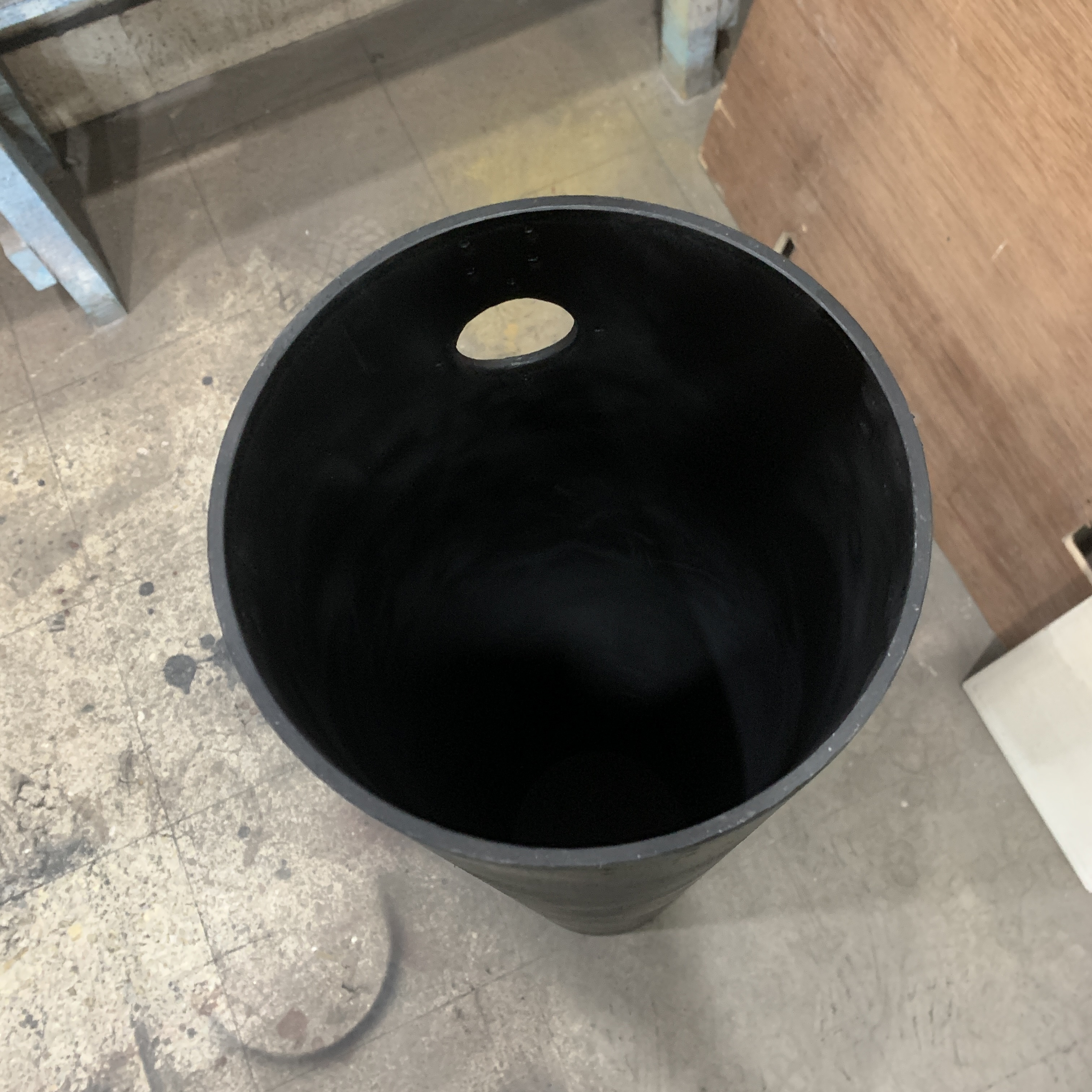
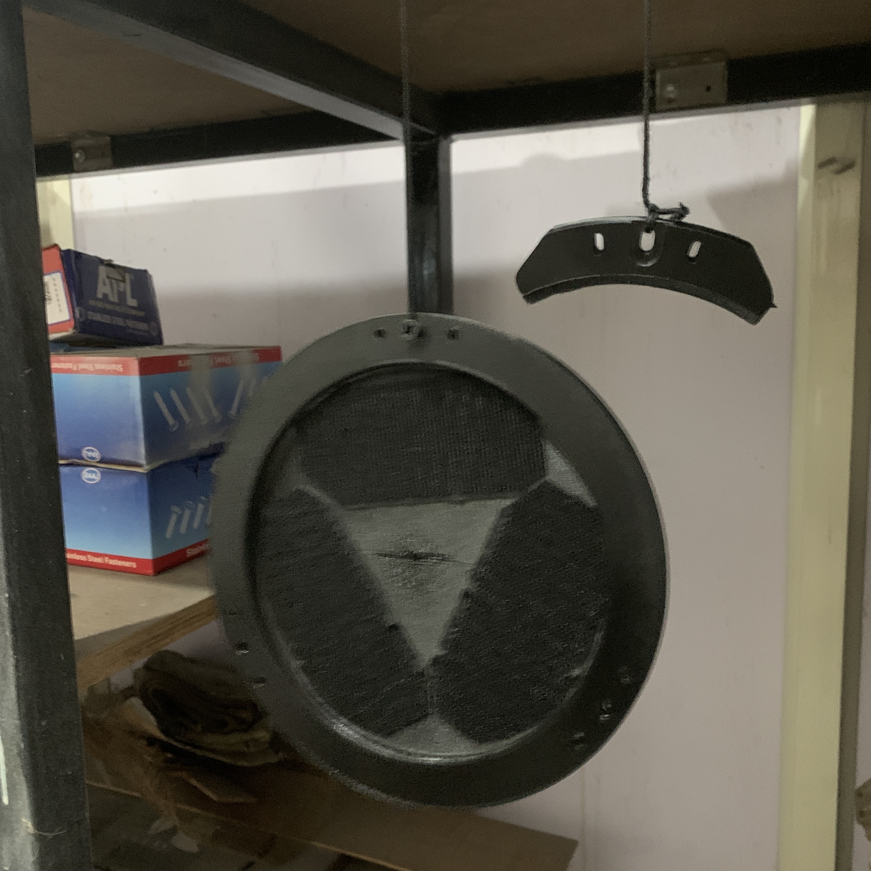
>> 03_OPTICAL TUBE ASSEMBLY (OTA)
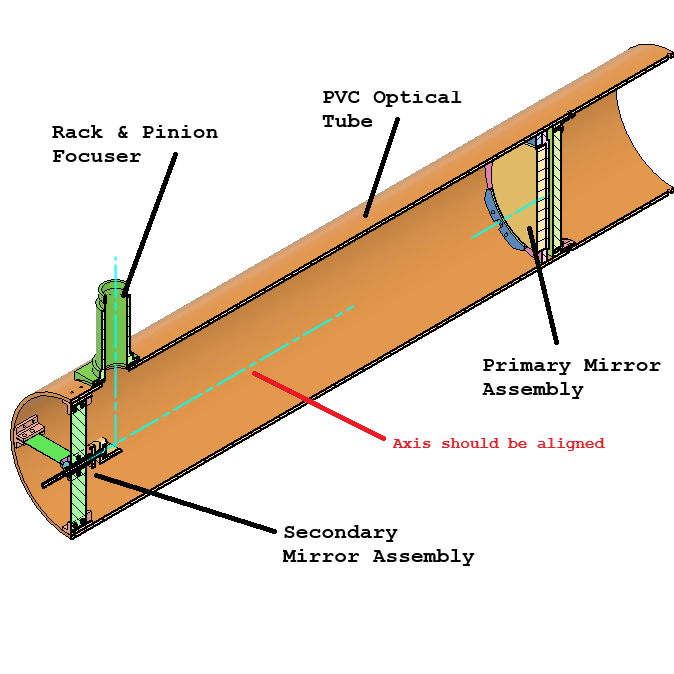
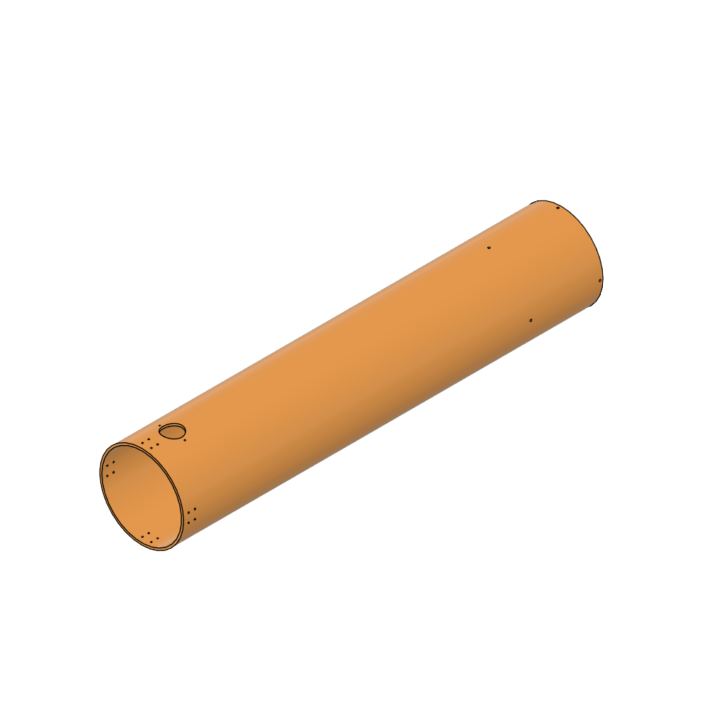
Based on the images represented above:
- The OTA is a PVC tube purcahsed from a hardware store of dimensions
- Height or Length: 1000mm
- Outer Diameter: 200mm
- Inner Diameter: 190mm
- The holes positioning were hand drilled based on the calculations that was done above.
- Collimation can be done later, ensure all the brackets are fastened properly and the length of fastener should not exceed the 20mm offset i.e., 20mm space between mirror and the inner diameter of the tube.
- CAD Link: GRABCAD - Curiosity
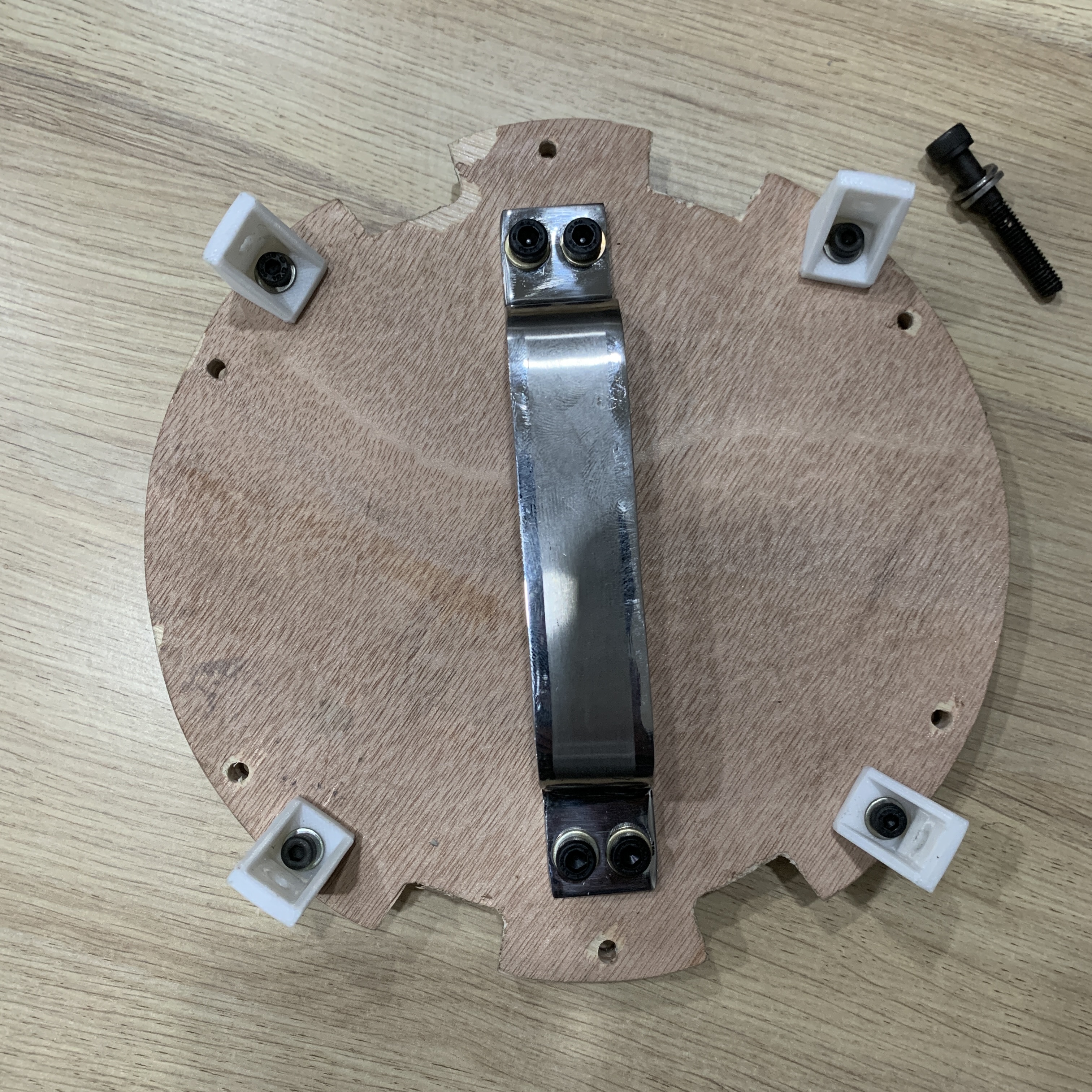
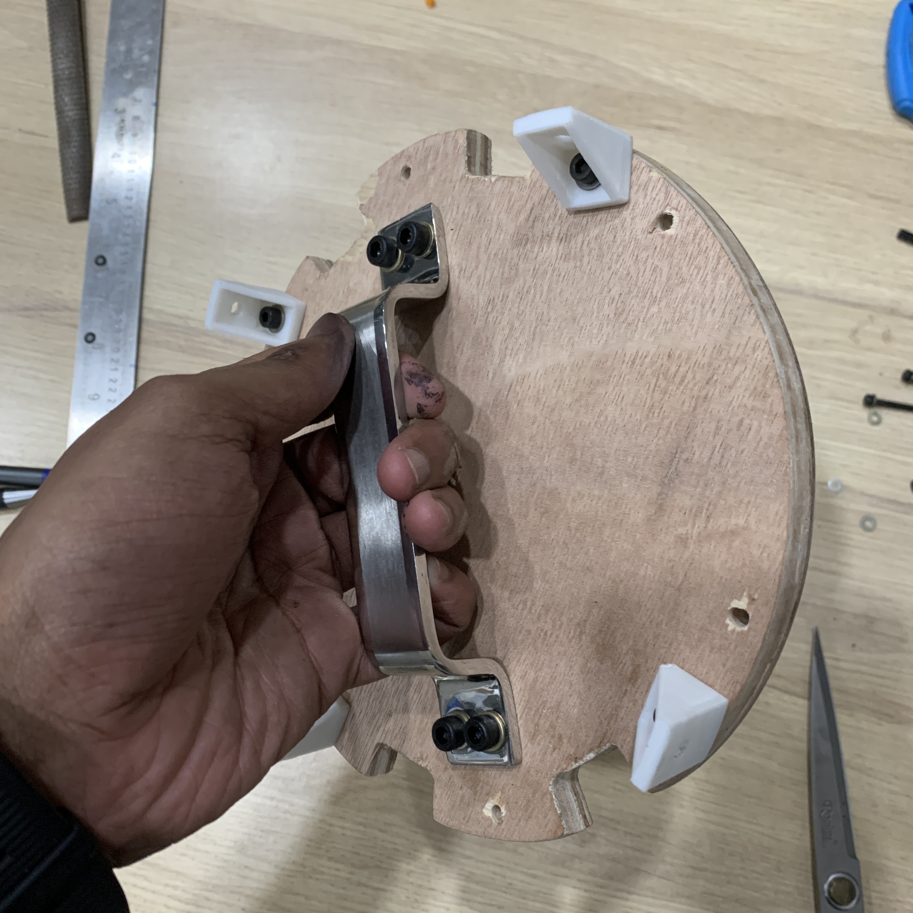
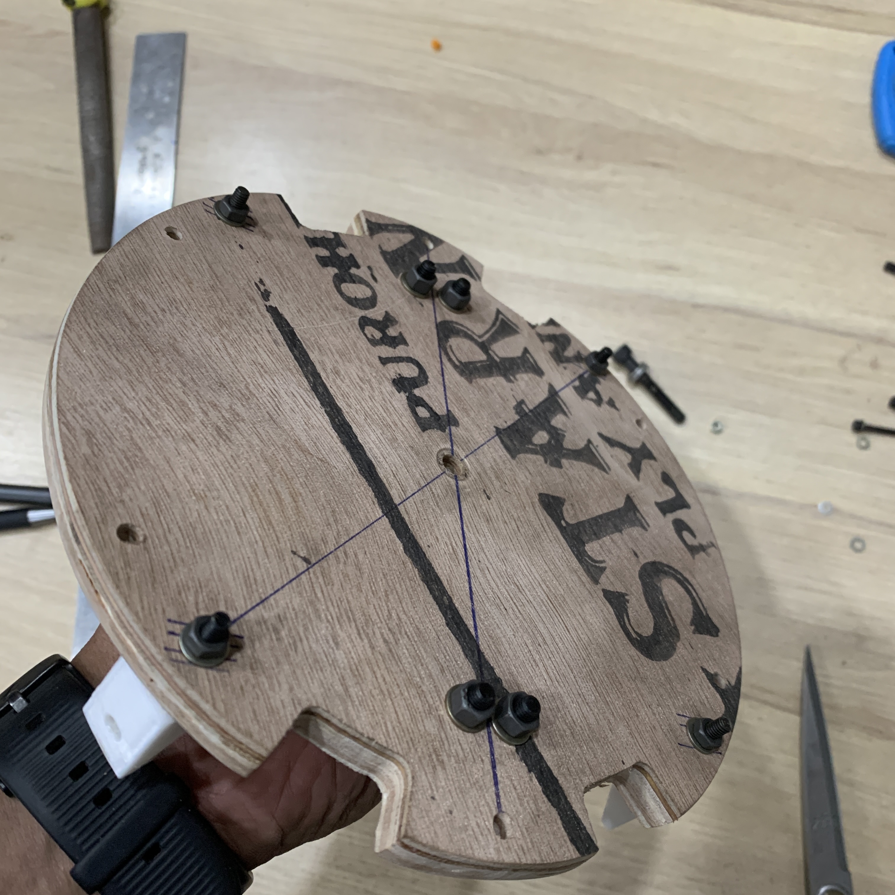
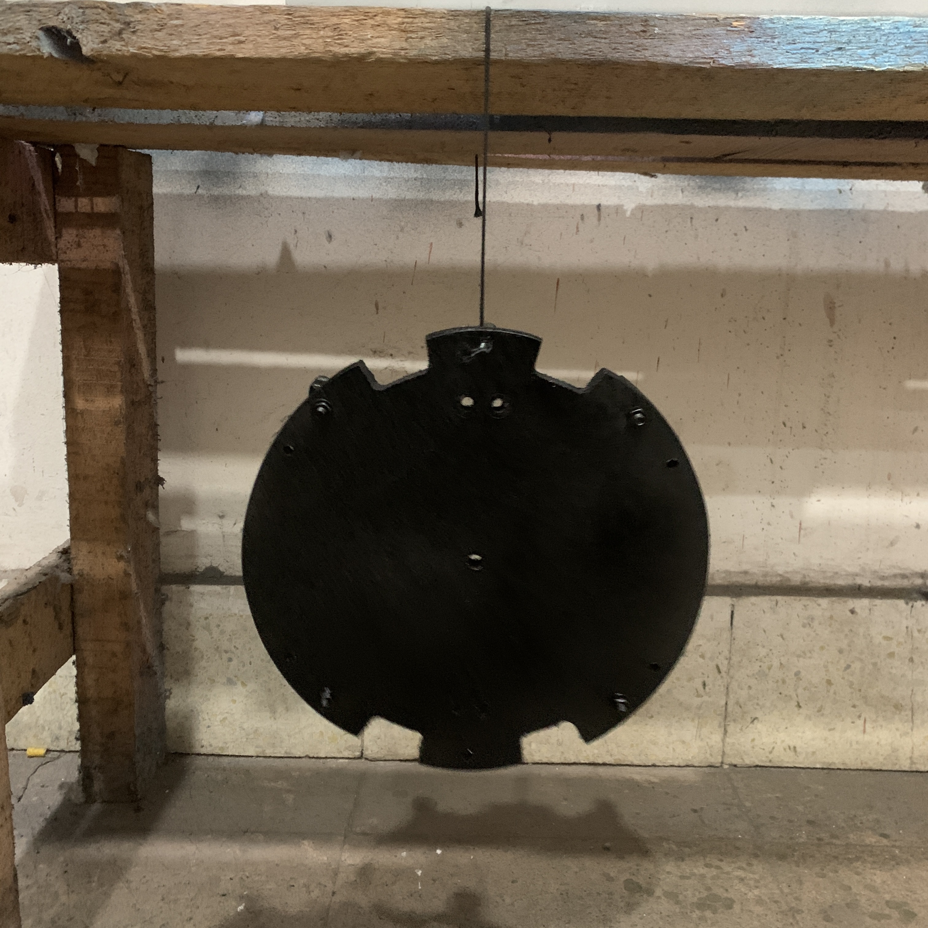
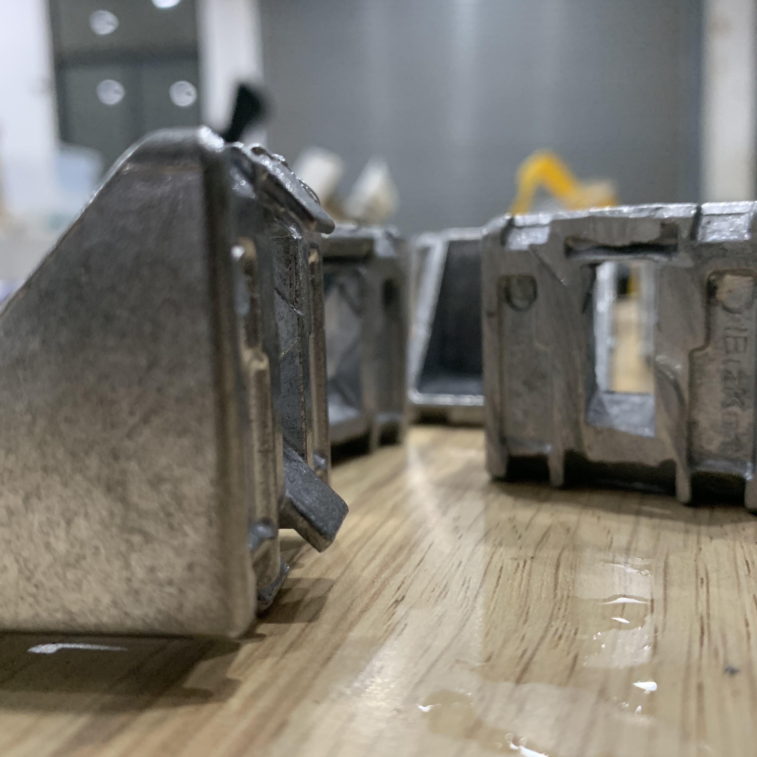
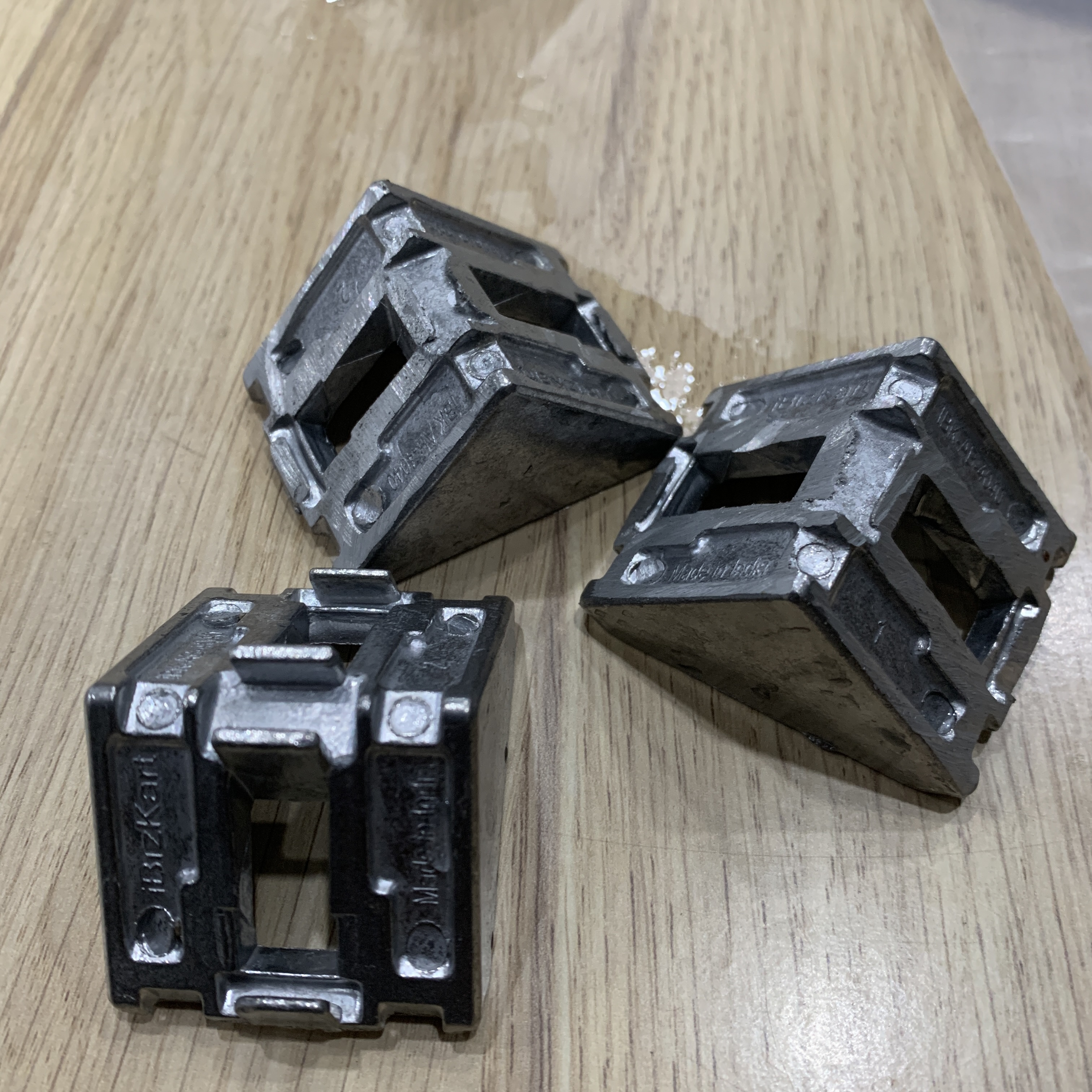
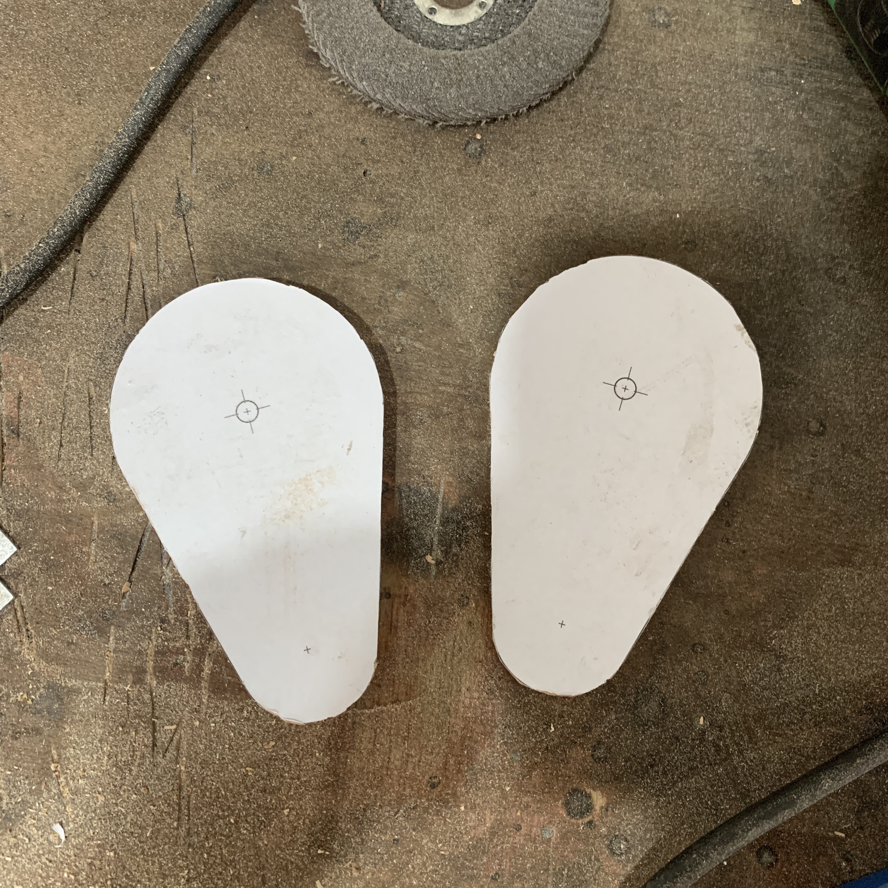
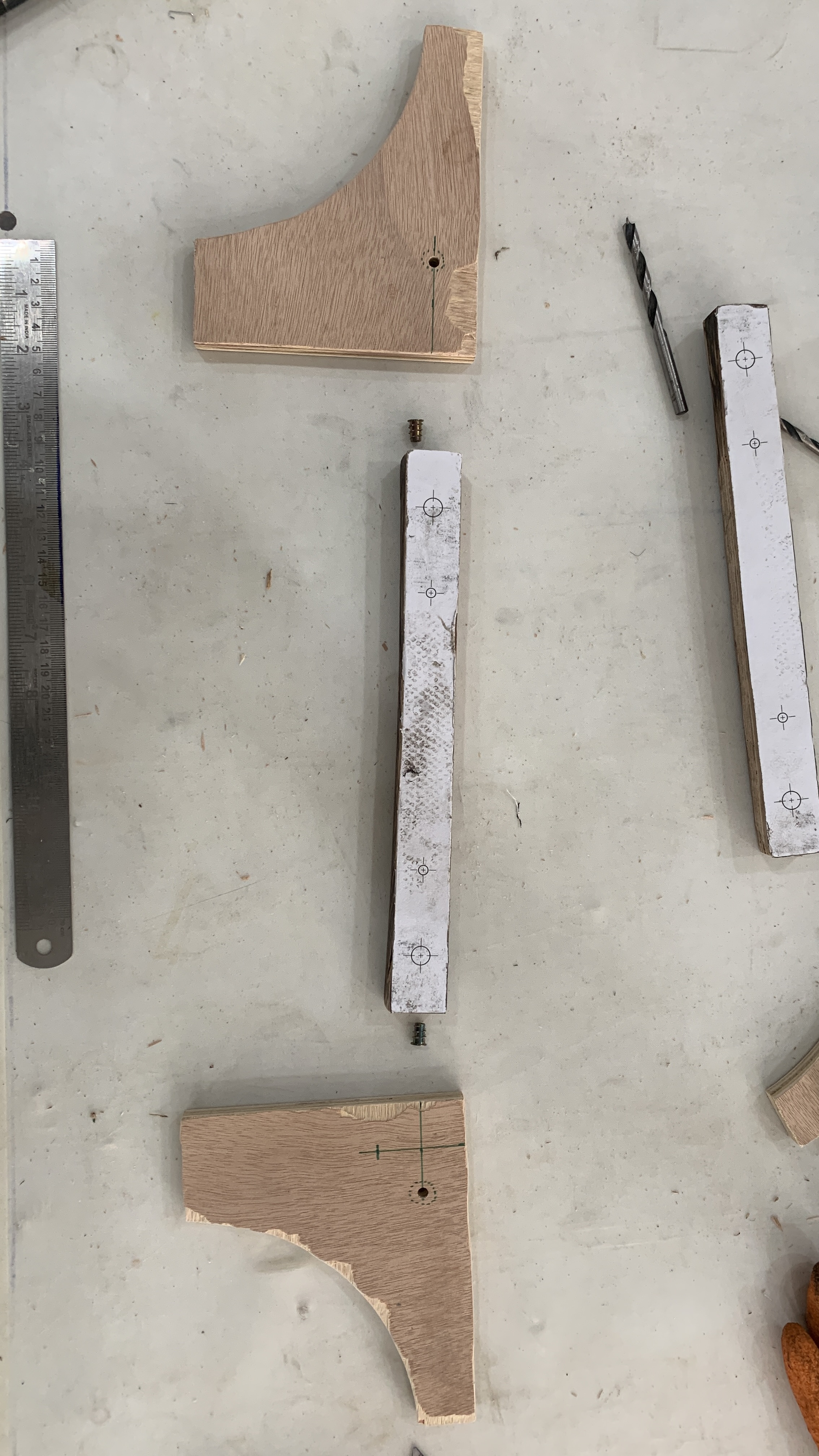
>> 04_OTA CRADLE
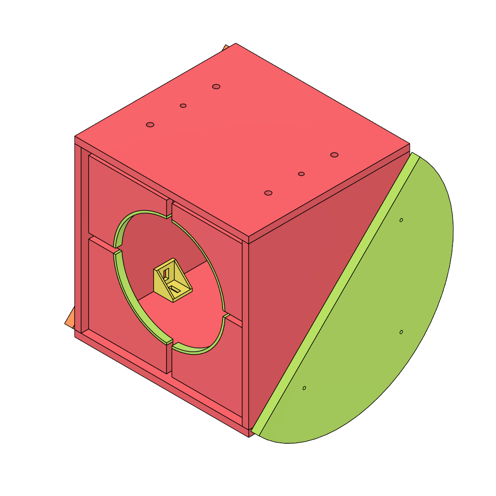
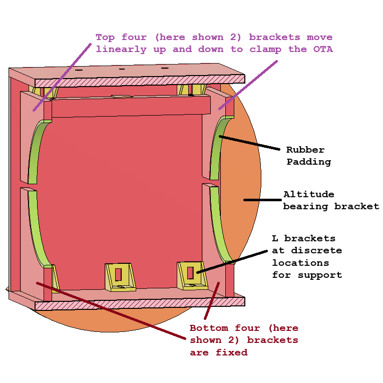
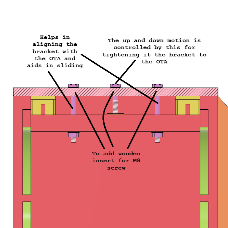
Based on the images represented above:
- We were heavily inspired by >> Stellafane's Guide
- Complete OTA Cradle is made with plywood cutout and held together with
- Firstly with Aluminium profile L brackets.
- Secondly all the mating surfaces were connected with self tapping screws for wood.
- To ensure the entire cradle is sturdy with supports.
- CAD Link: GRABCAD - Curiosity
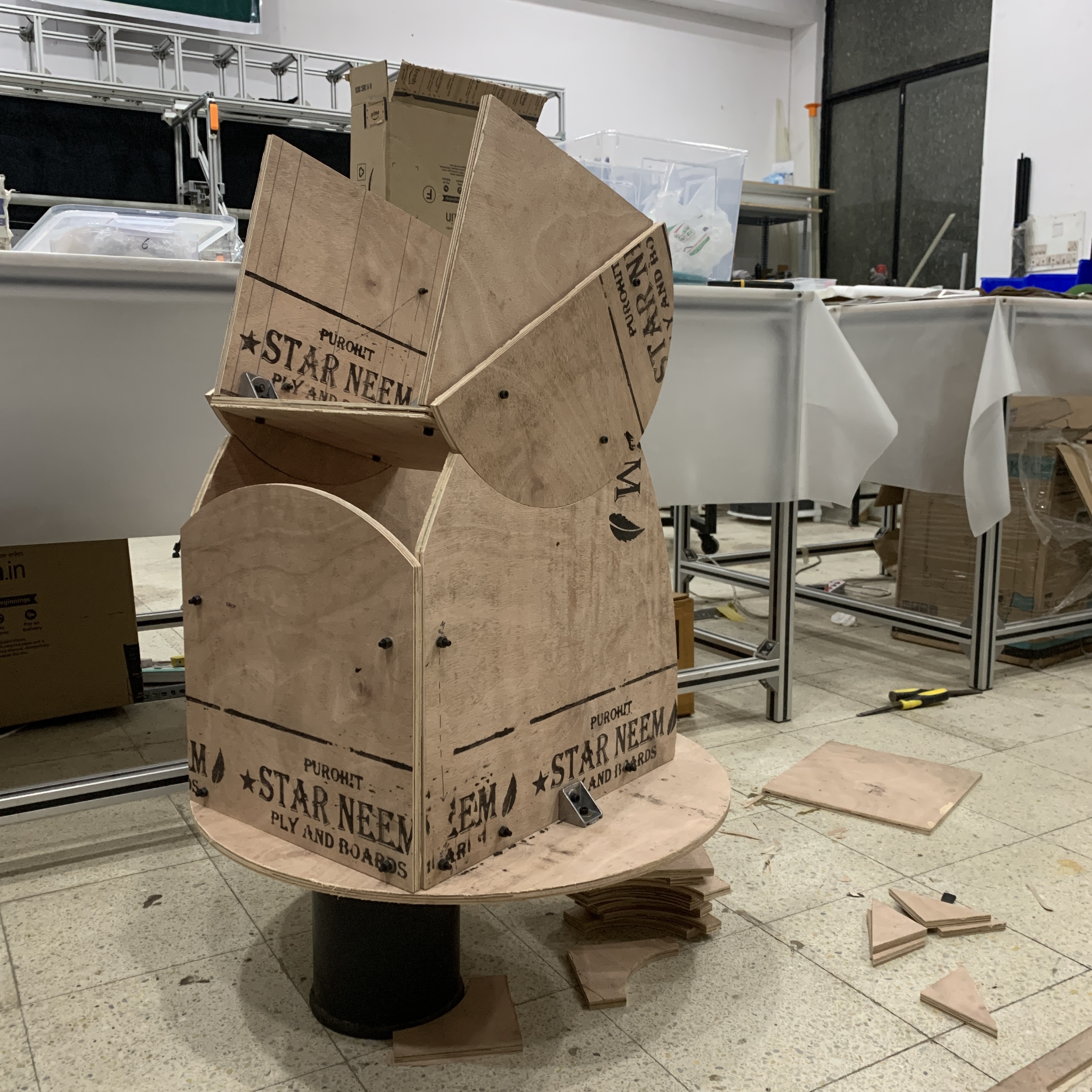
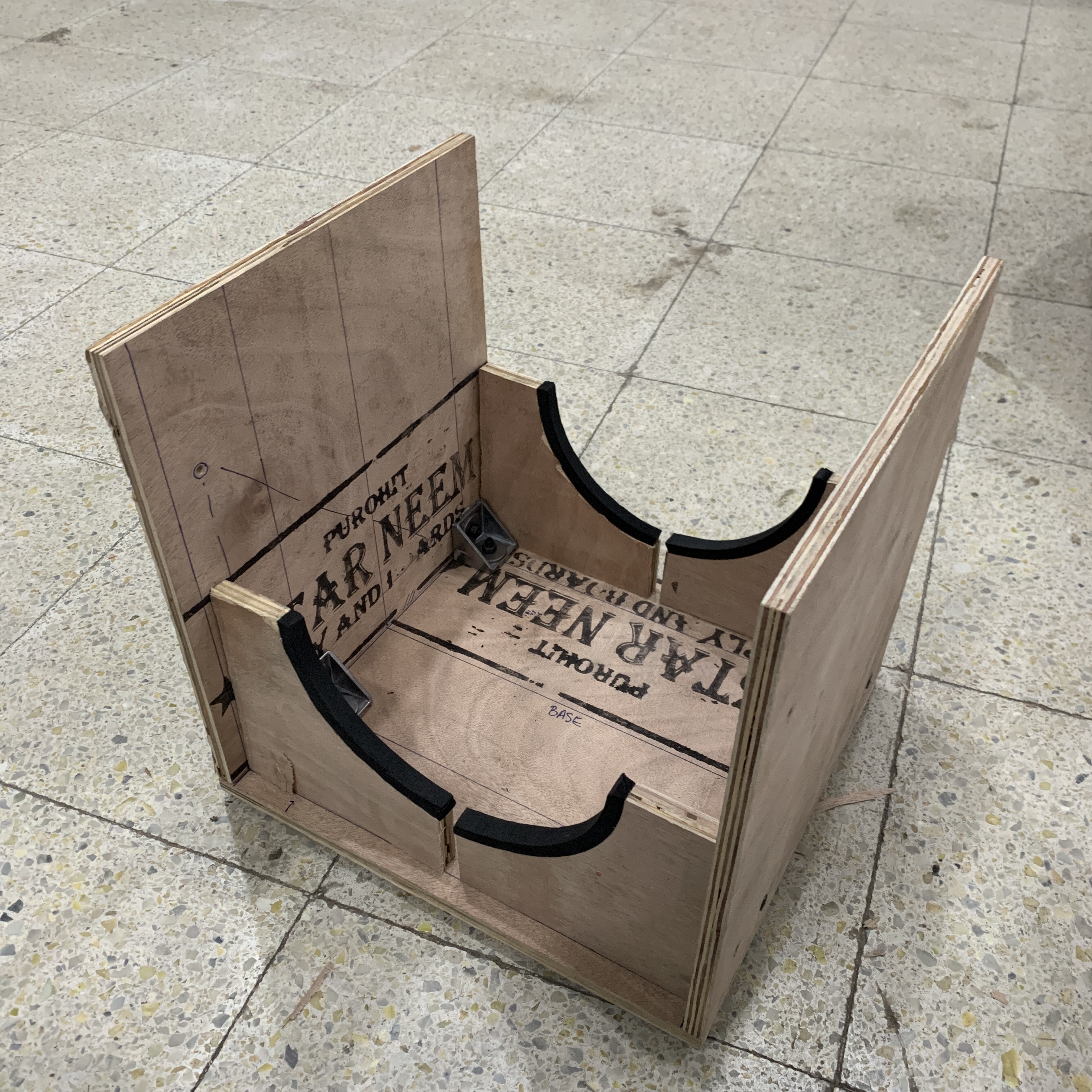
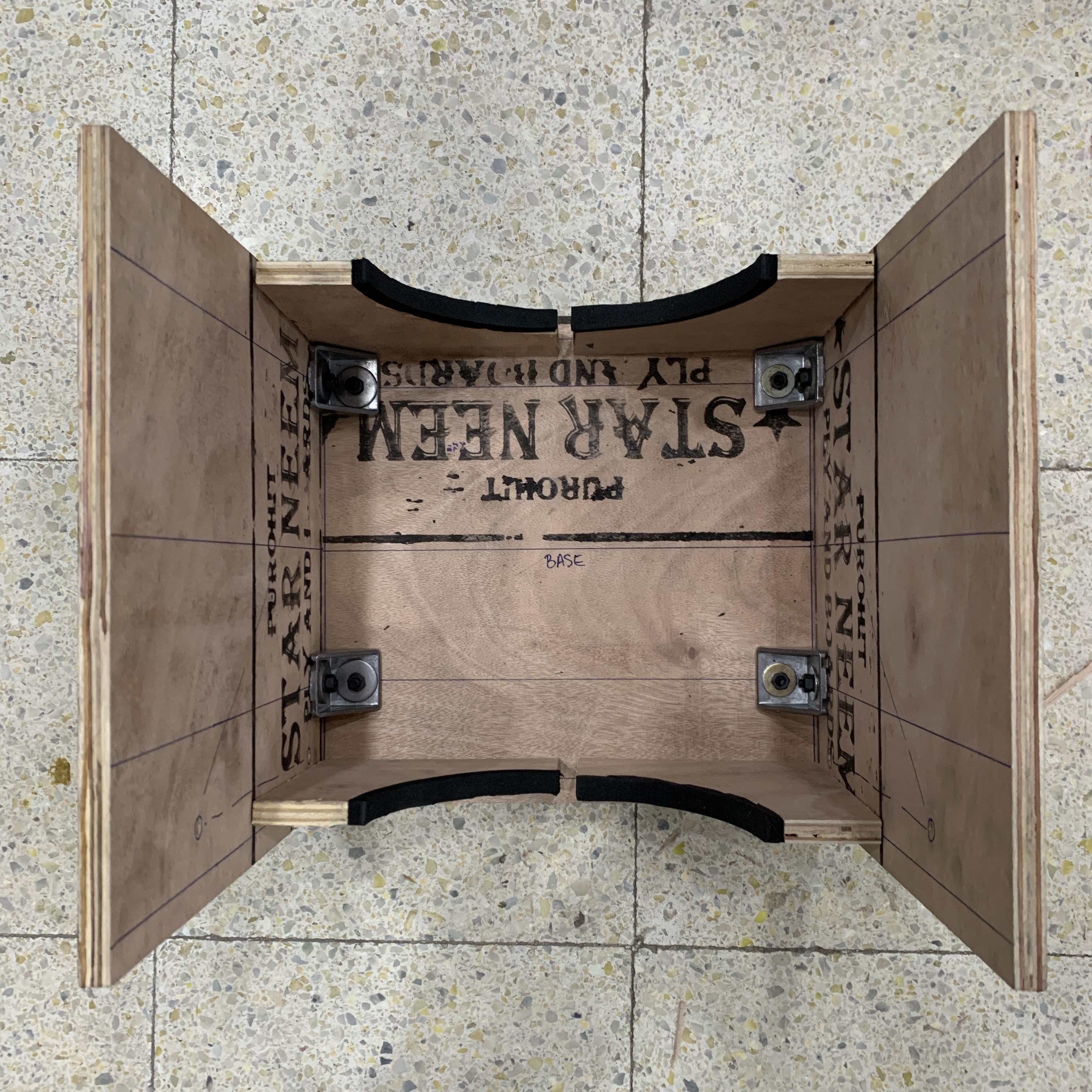
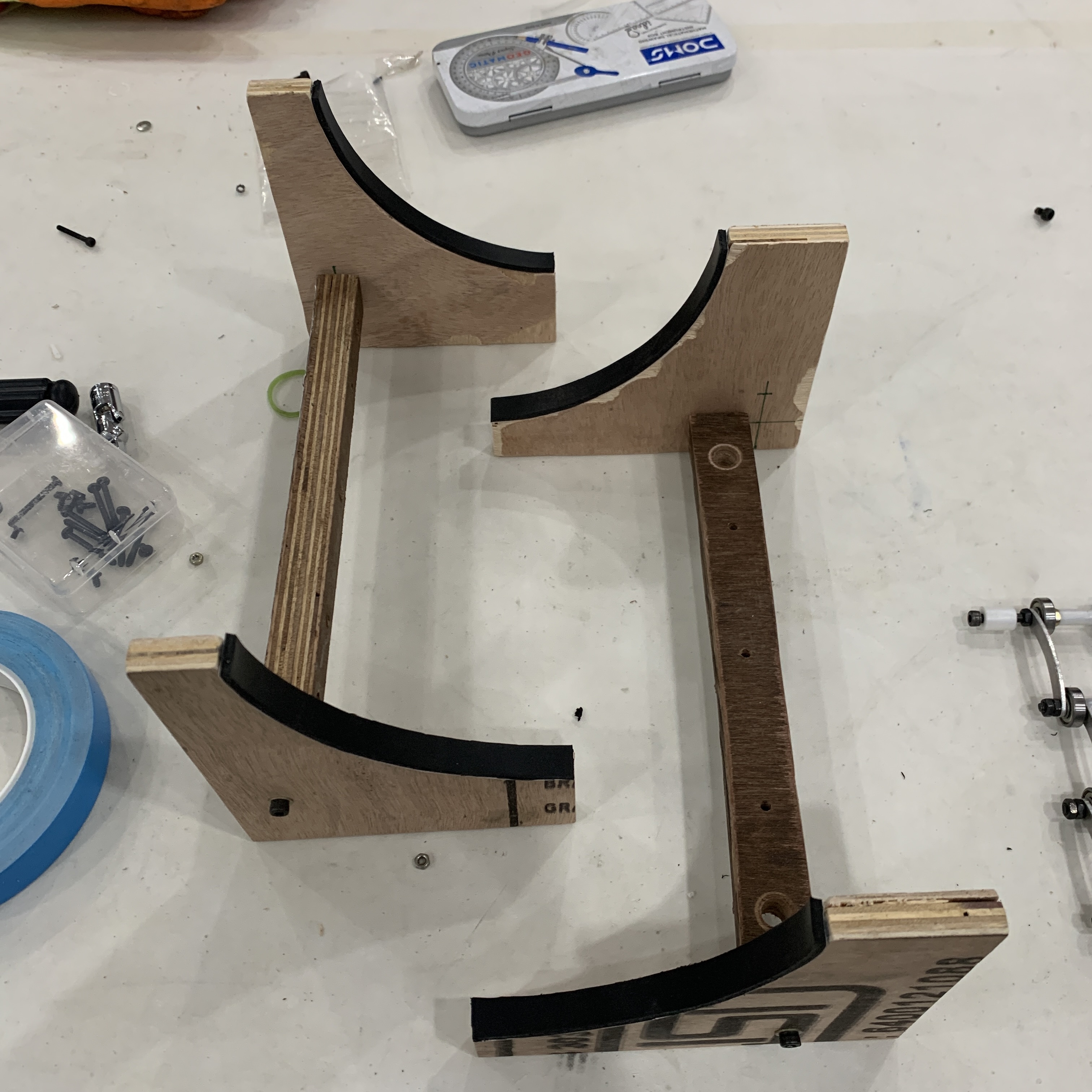
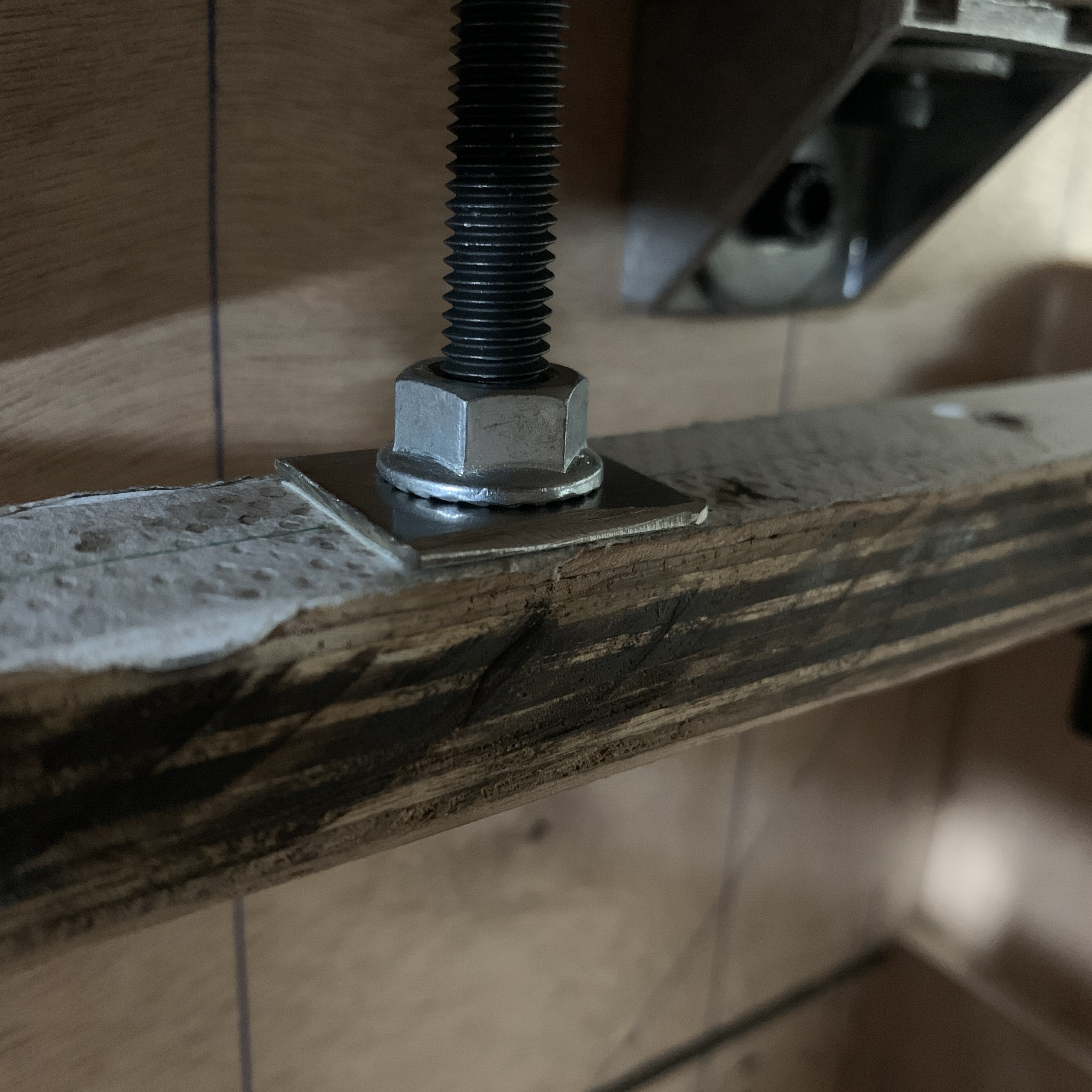
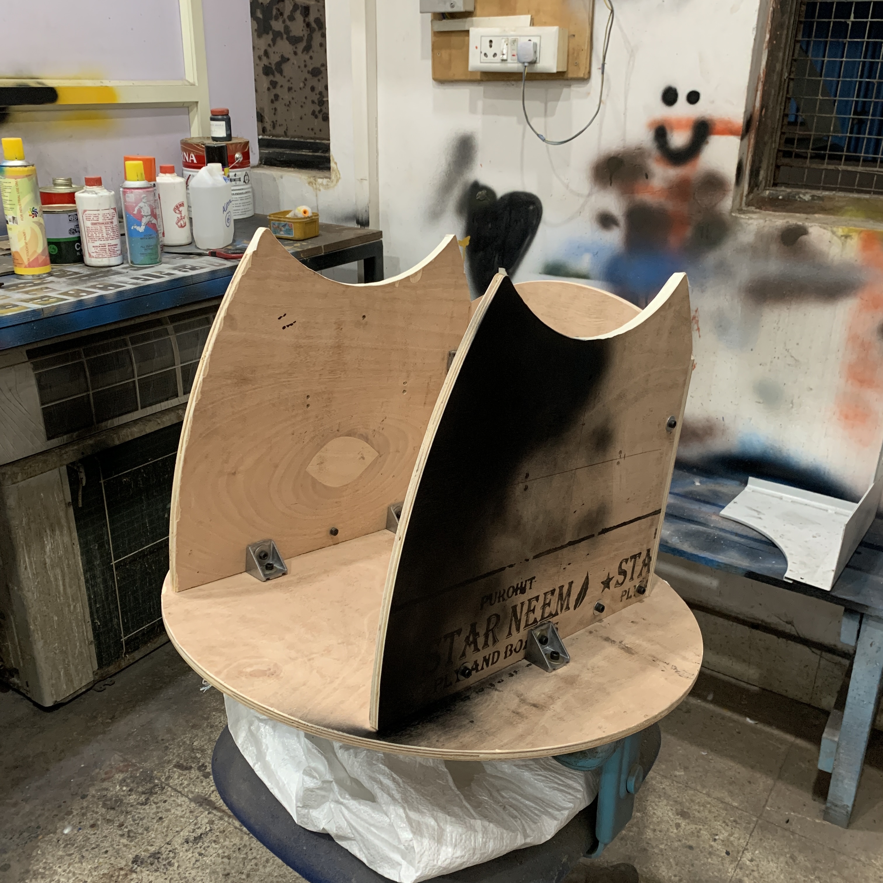
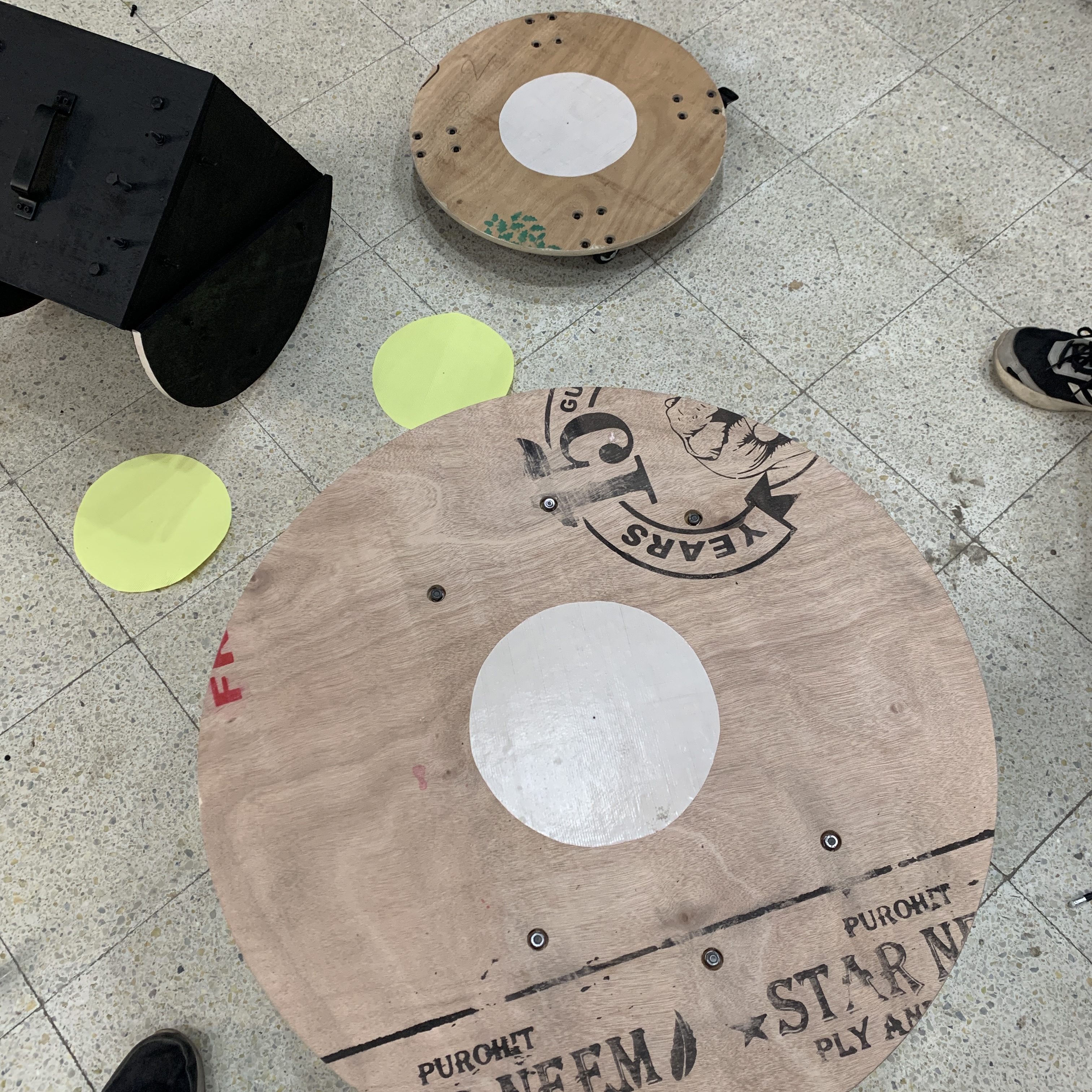
>> 05_ROCKER BOX
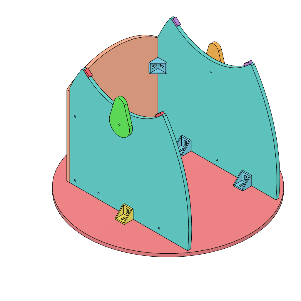
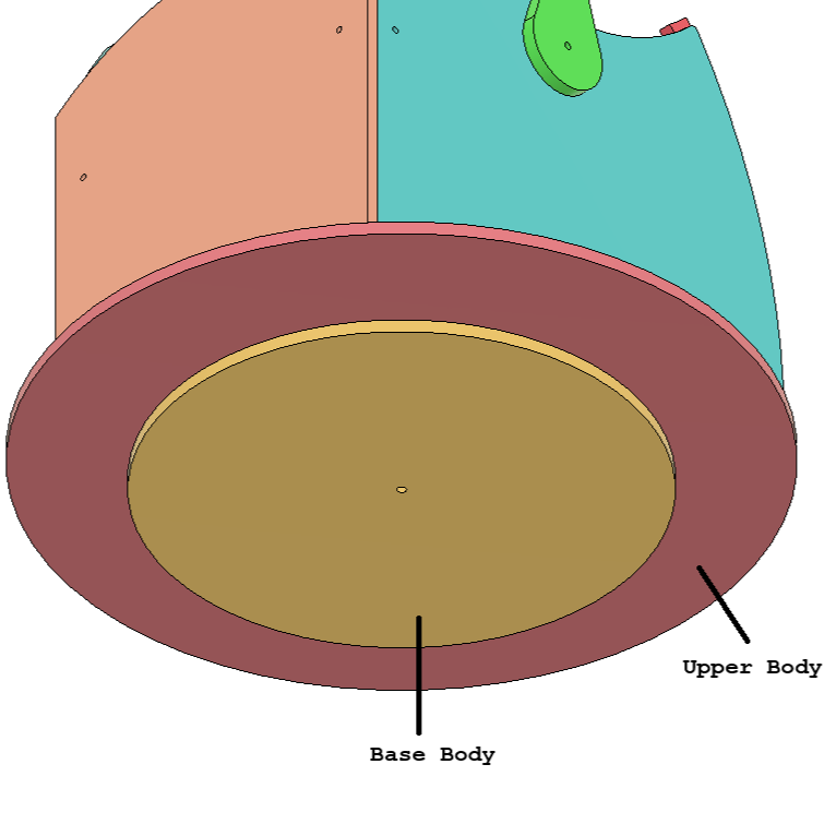
Based on the images represented above:
- We were heavily inspired by >> Stellafane's Guide but gave our own touch to the overall design.
- Complete Rocker box is made with plywood cutouts held together with L brackets at multiple locations.
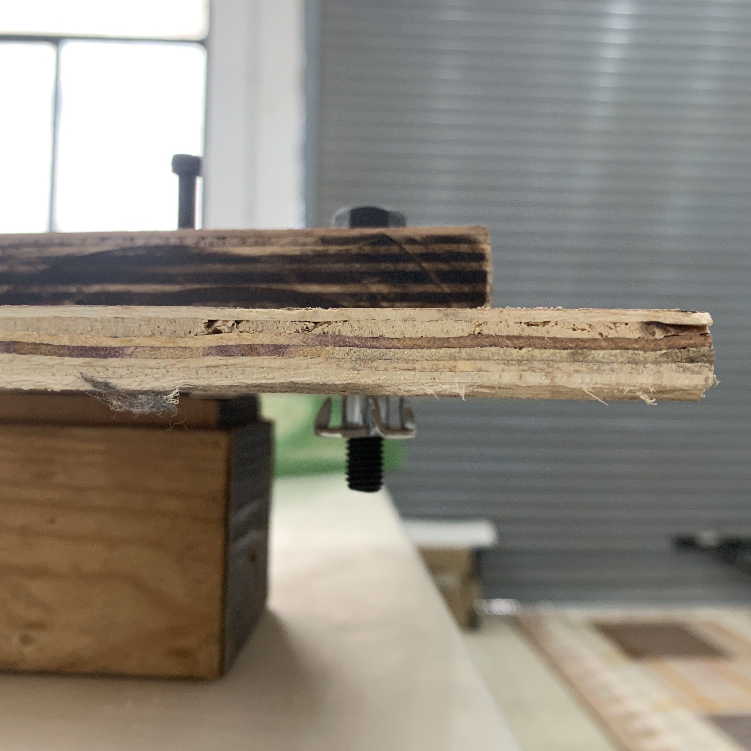
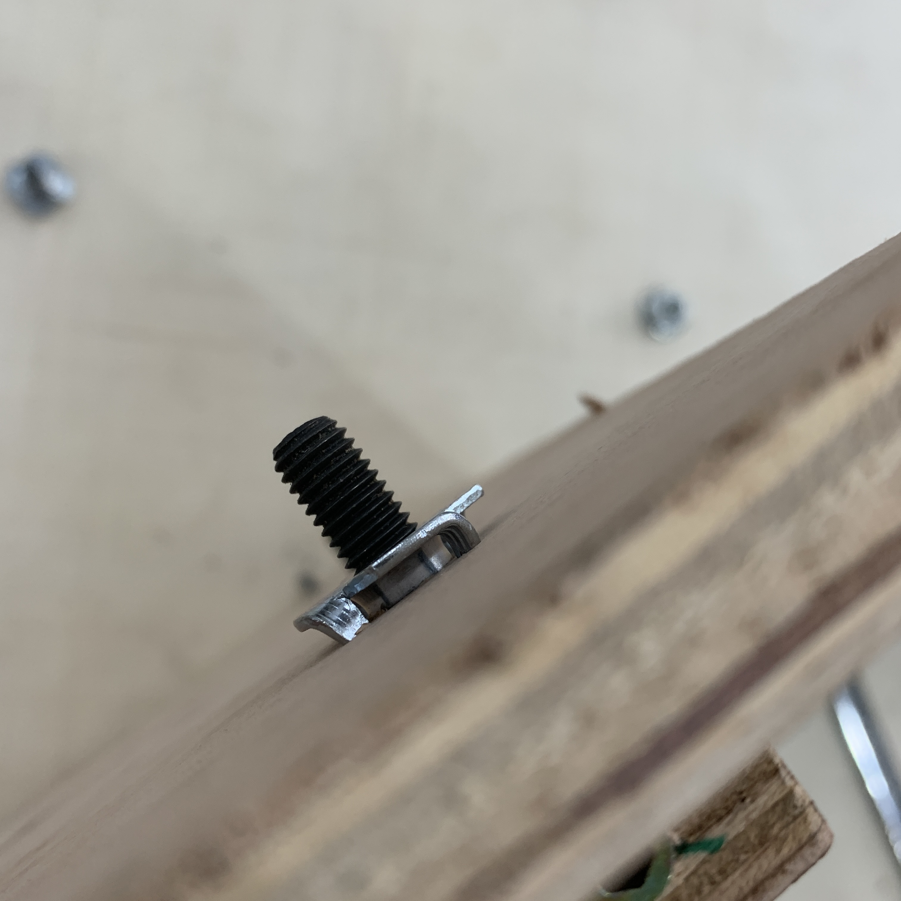
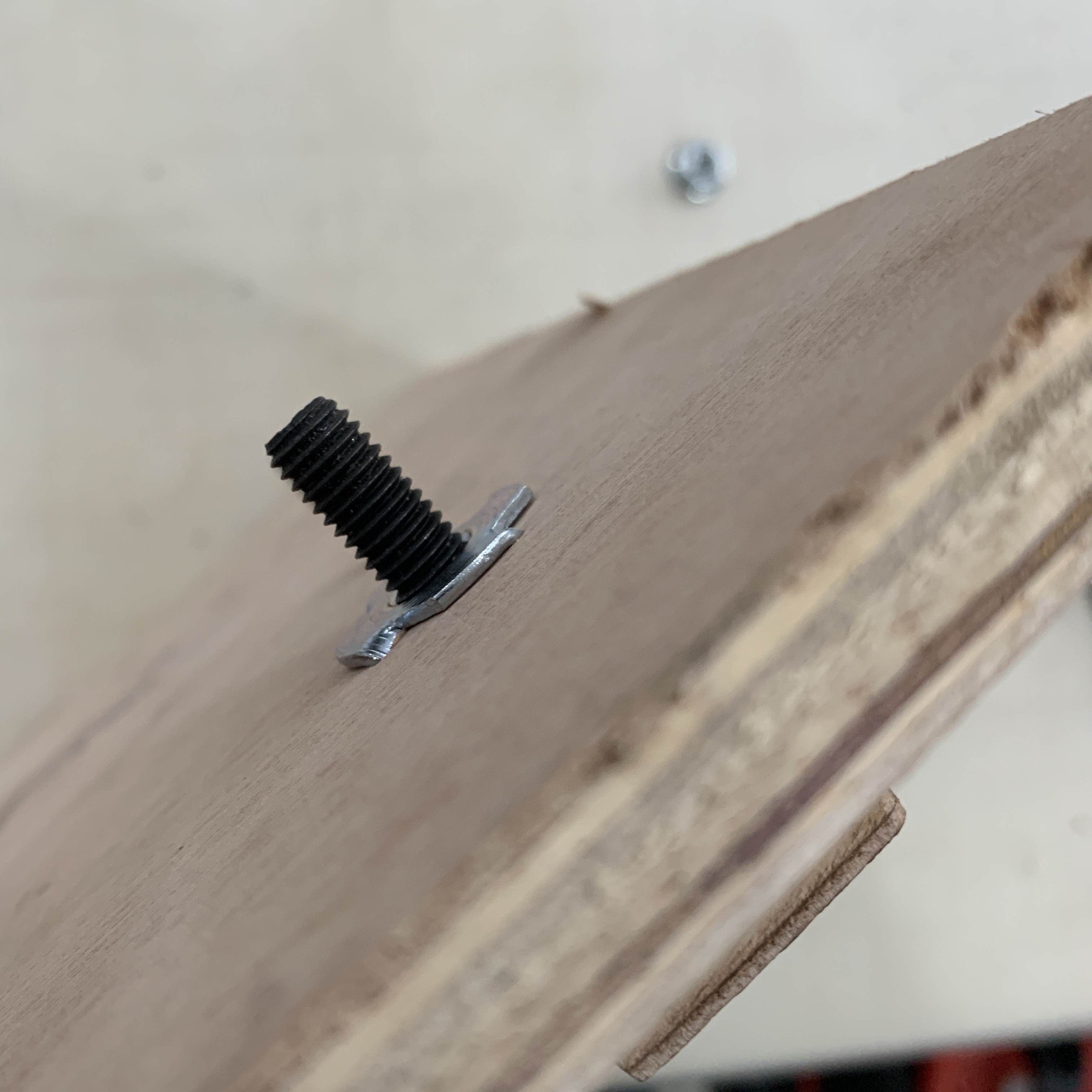
- For smooth rotation, the base body and the upper body can be connected with
- Compact disk
- Roller bearings
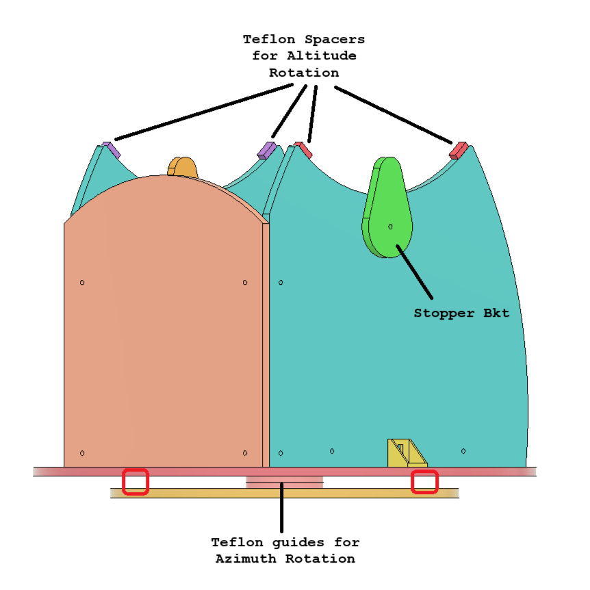
- Teflon spacers sliding over each other, but ensure as shown in the second image about a mistake that we did using a very small teflon disc which led to imbalance issues. The red regions have been marked to highlight supports that need to be ensured.
- Our initial attempt incorporated using a teflon tape which was adhered to both the bodies but we wanted better smoothness in terms of rotation.
- The two bodies should be then clamped with a fastener.
- CAD Link: GRABCAD - Curiosity
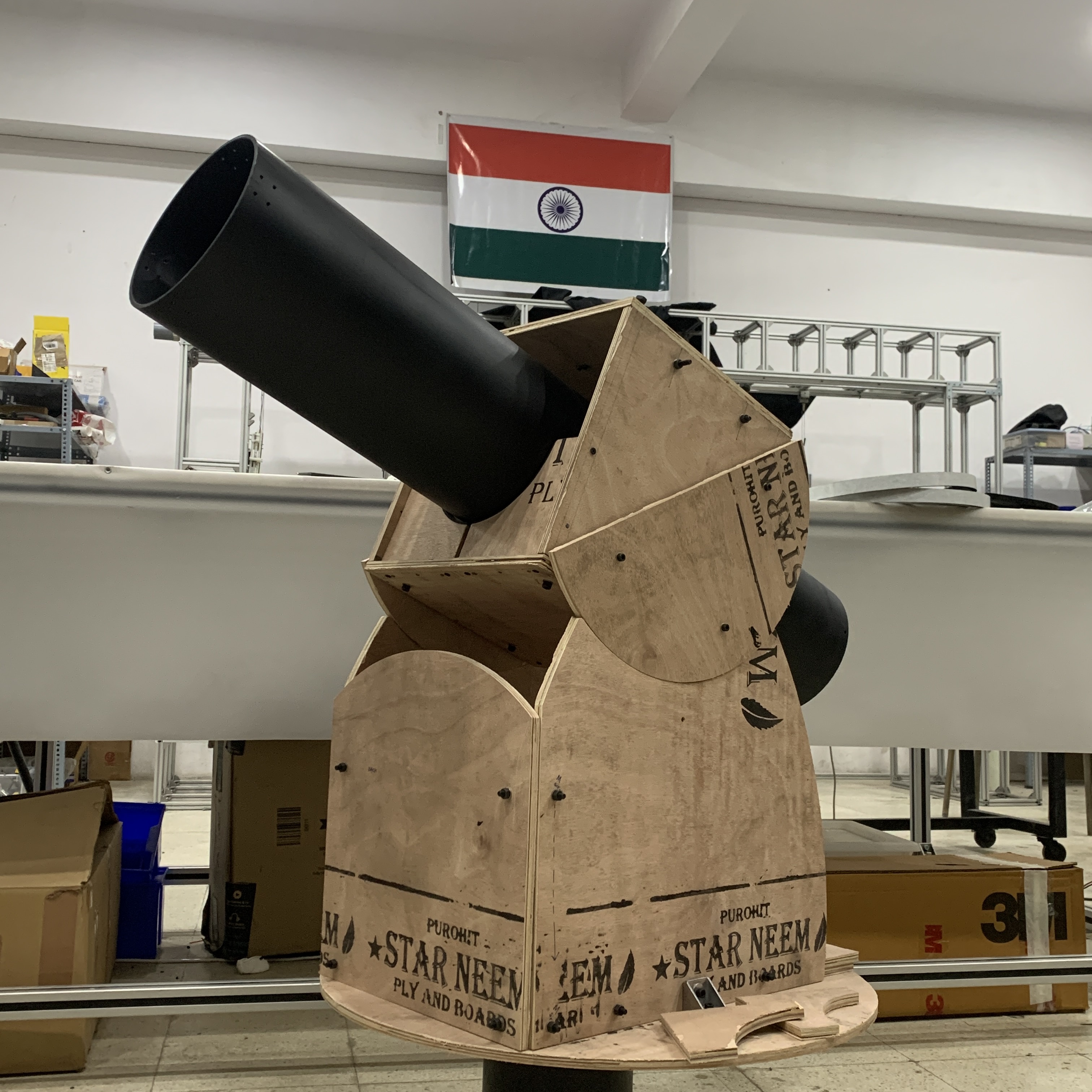
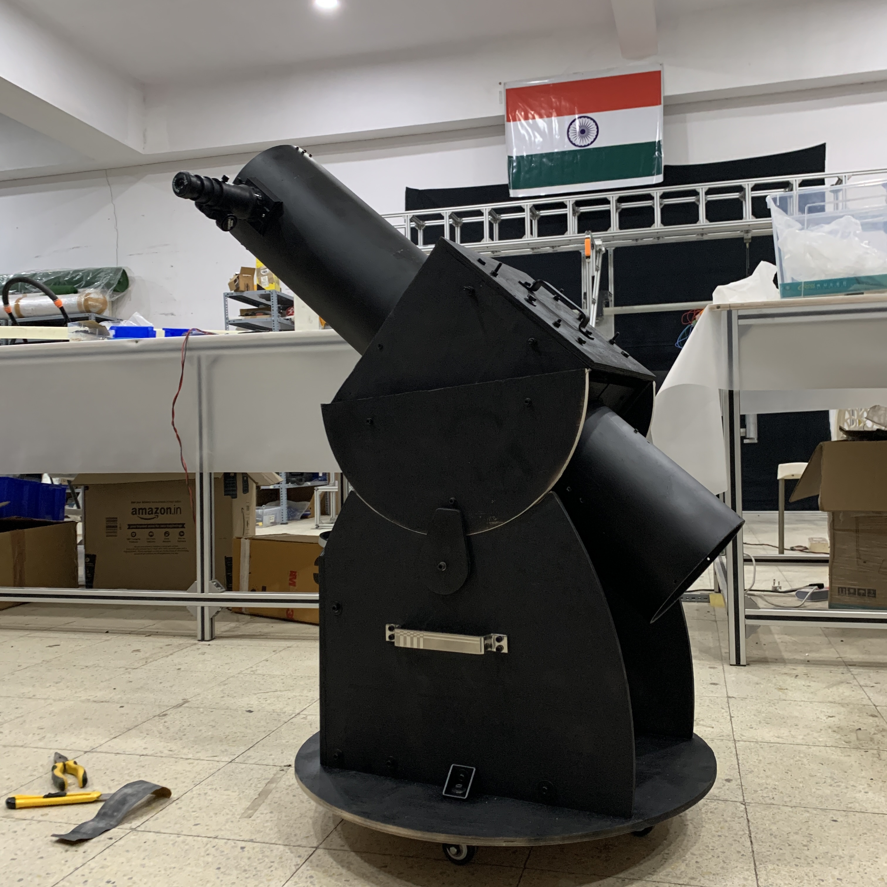
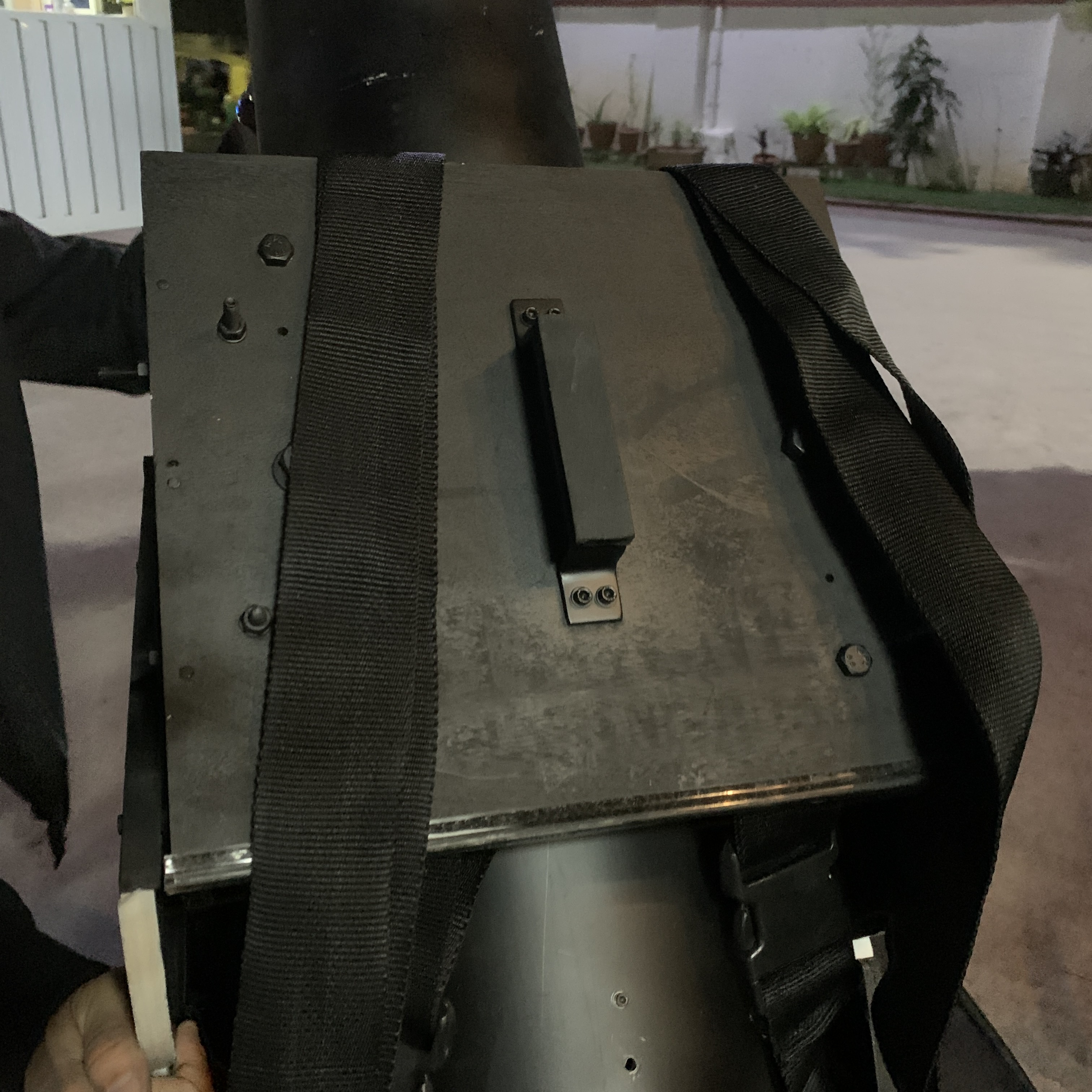
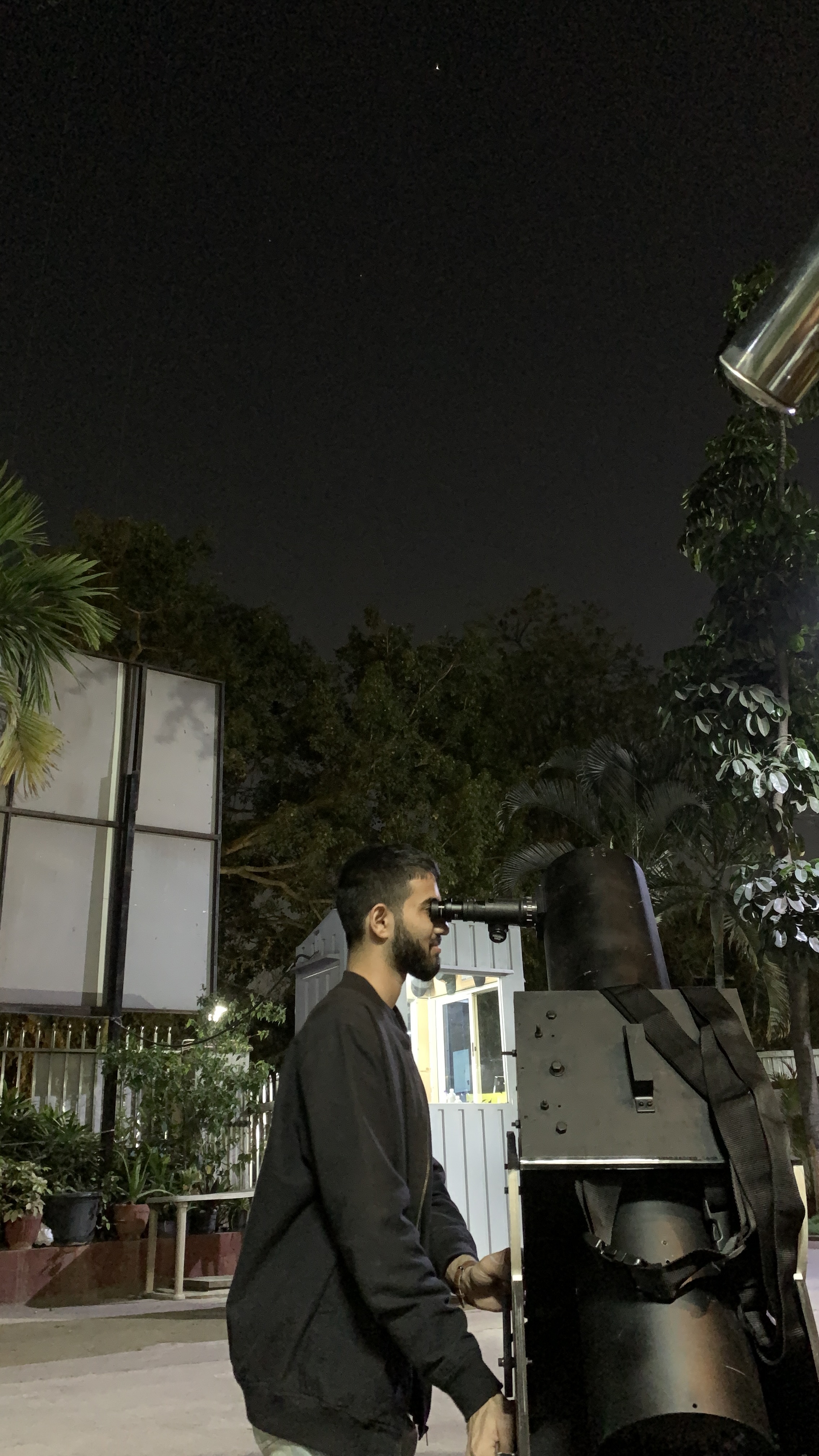
>> 06-FINAL TELESCOPE ASSEMBLY
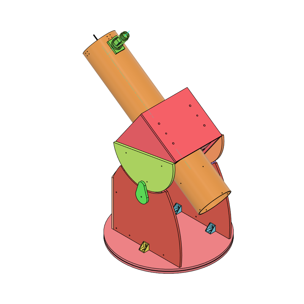
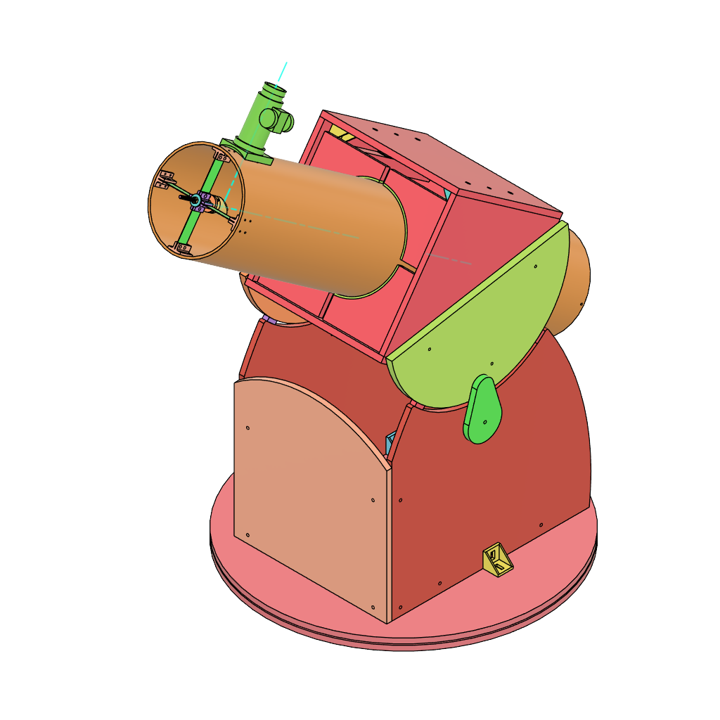
- CAD Link: GRABCAD - Curiosity
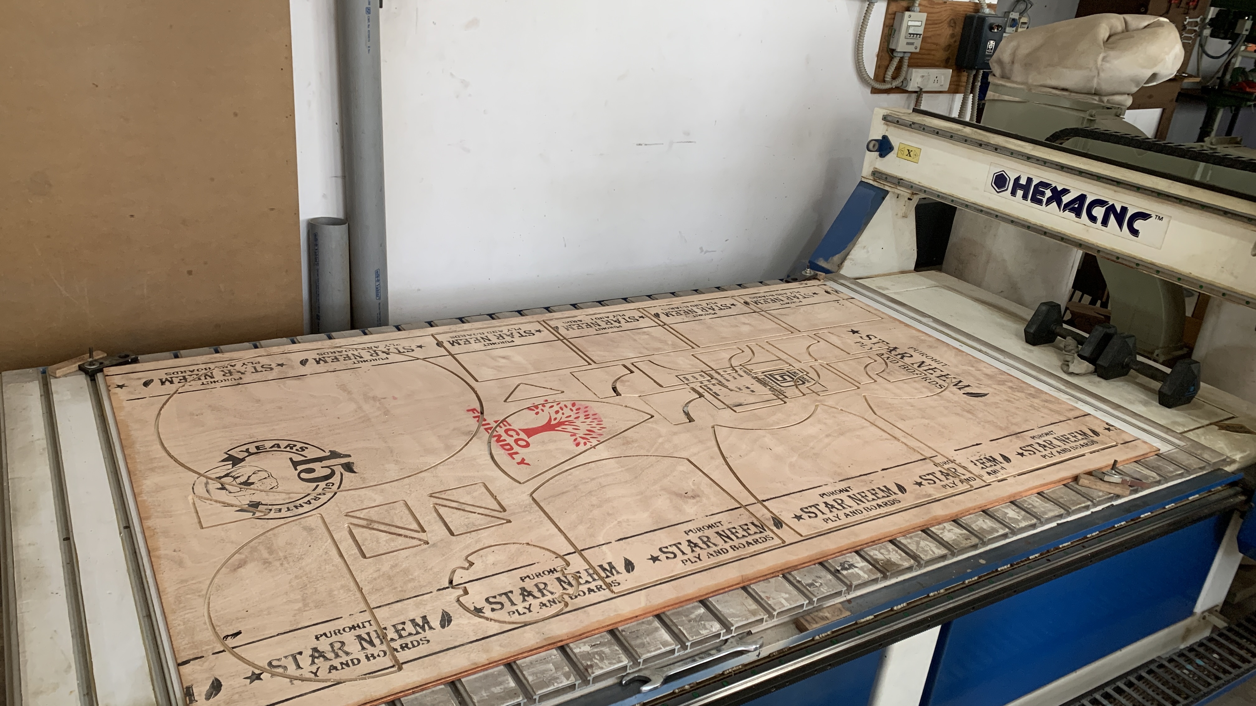
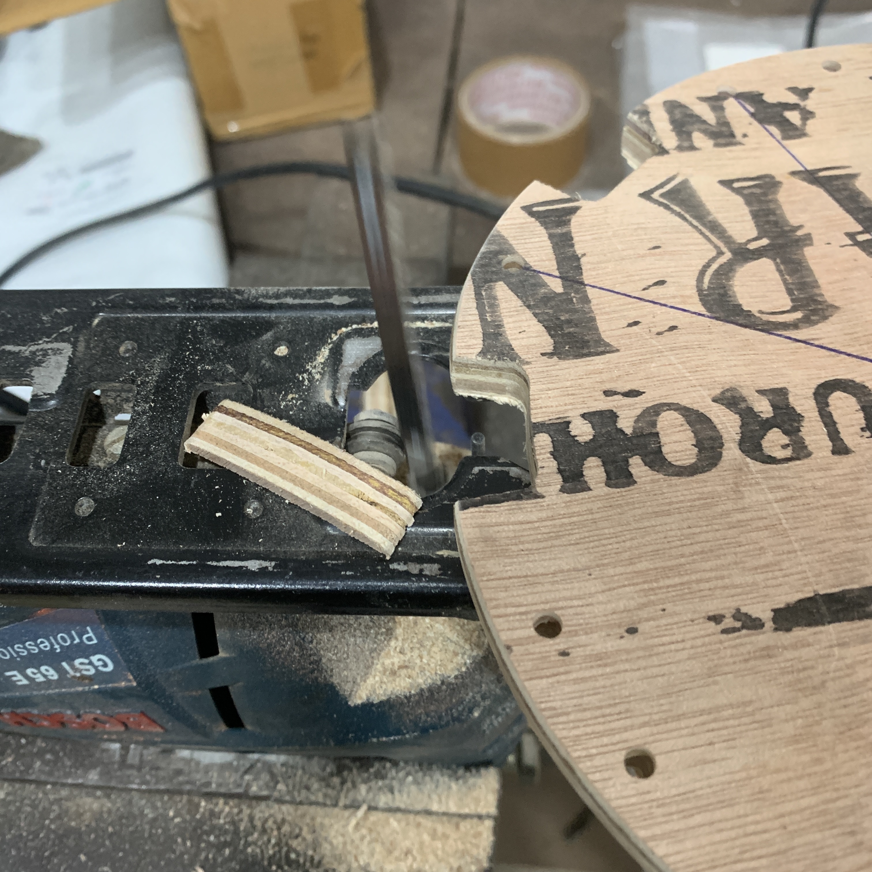
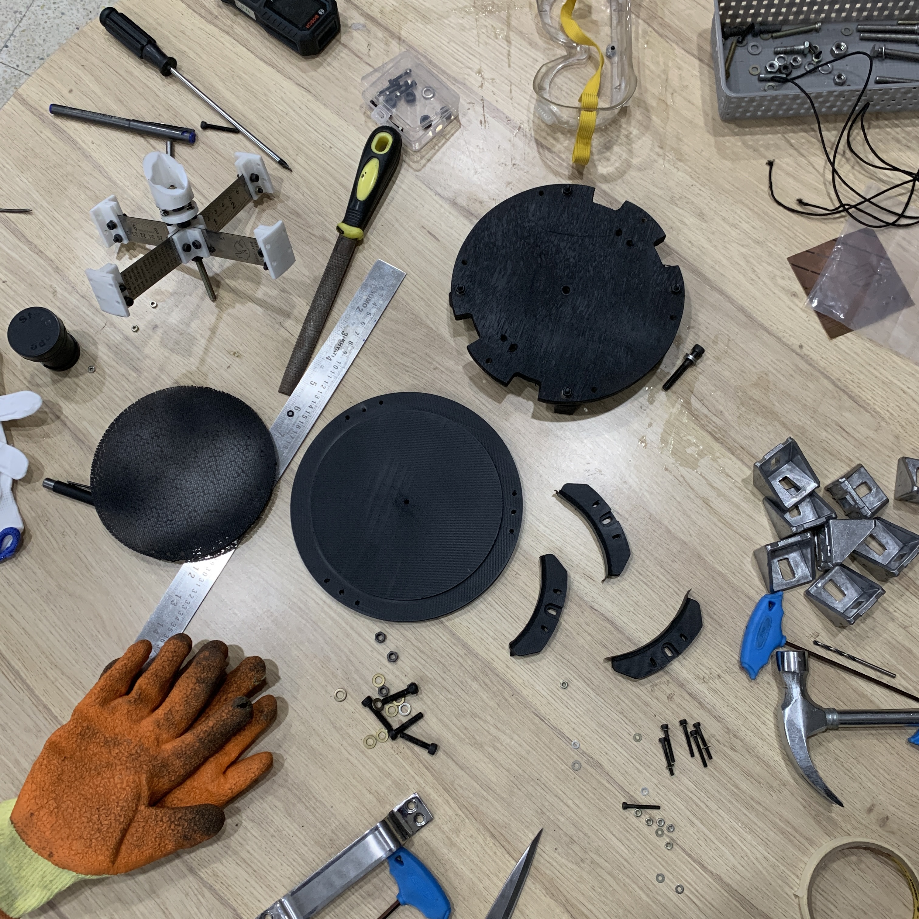
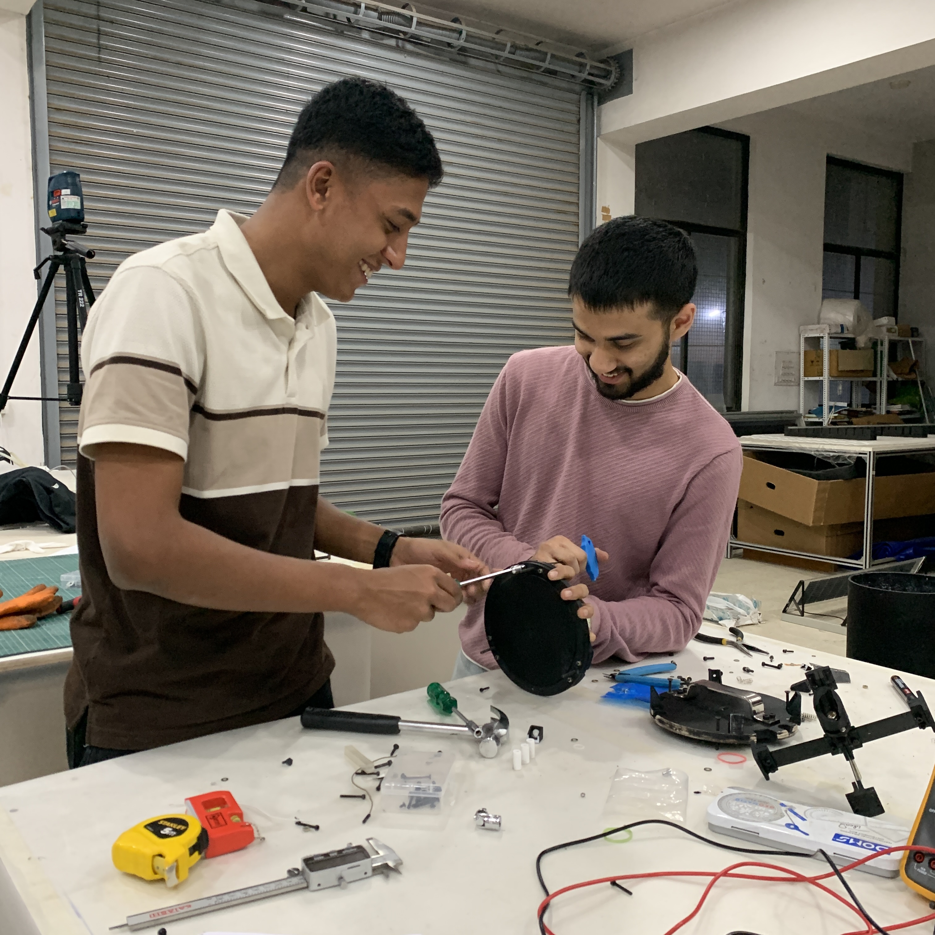
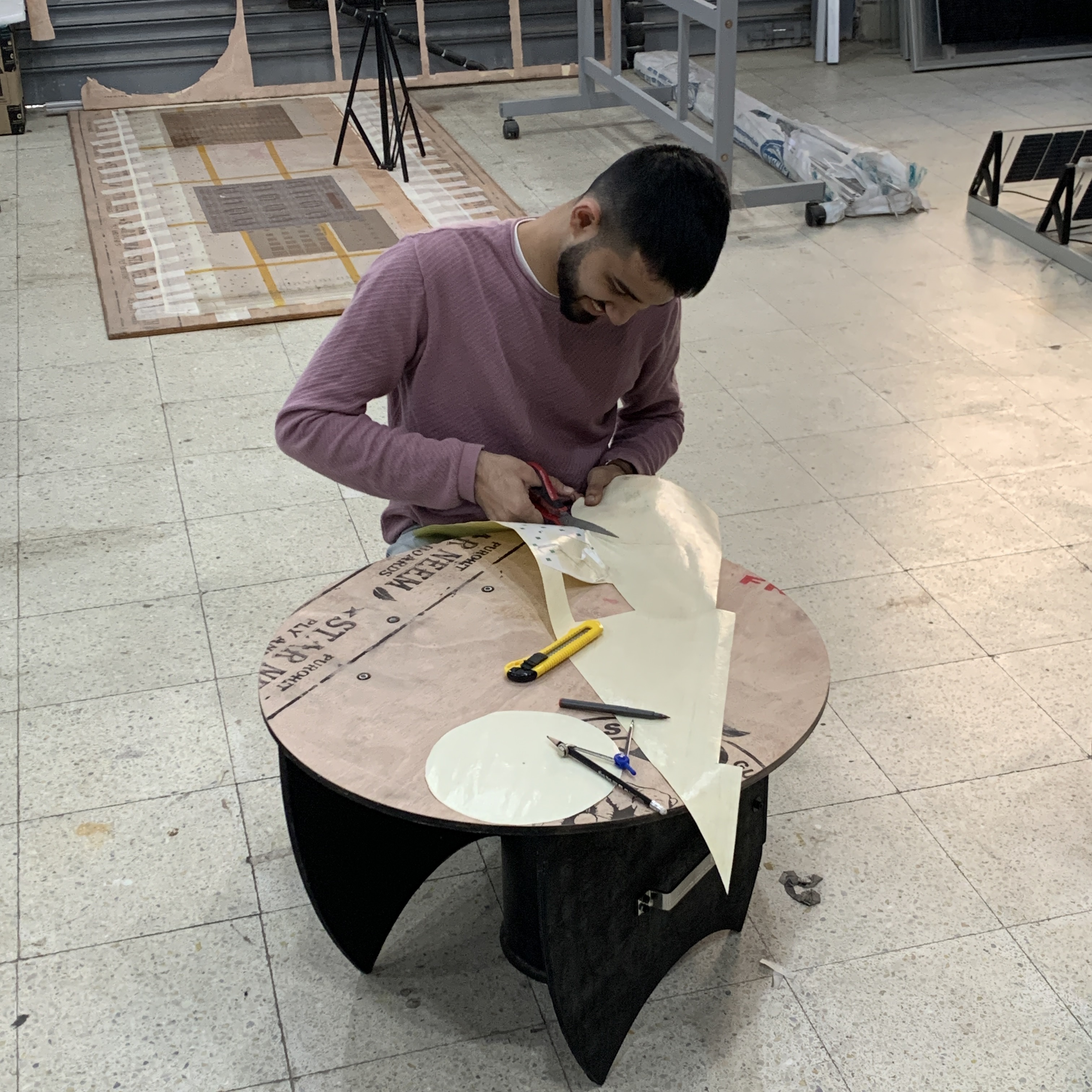
To get the assembly party started. From design to fabrication!
We were lucky enough to have access to a really big wooden router at our lab's facility. To make our life easier and pace up the process, we decided to utilize the capability of the wooden router for contour cuts of our desired profiles for telescope components.
What is this? Why is this? How is this?
This section highlights all the information that we came across to deepen our understanding pre-during and post assembly of the telescope. The aim is to put up information that will be helpful as and when we get to learn about something new. Happy Learning!
>> How do I learn the sky?
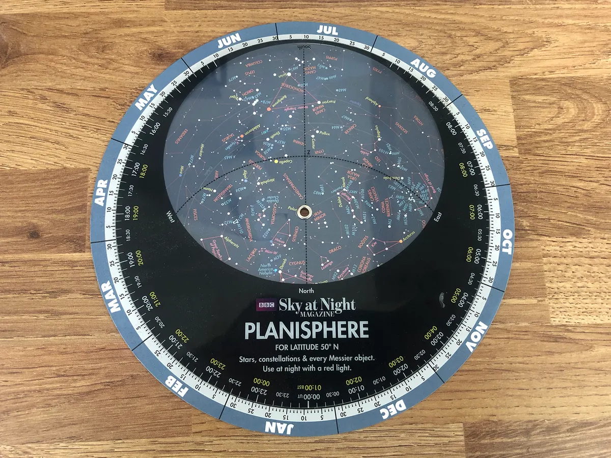
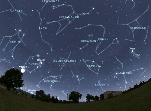

- Richard Berry in his book suggests, the best way to learn is via PLANISPHERE, wherein you can dial in the date and time and it will show you the sky at that instant.
- Following is a list of applications for IOS and Android that we came across, which should help you in navigating the skies
- IOS
- Stellarium
- SkyGuide - notifies you about any transits and also the best objects to look at the sky based on your location
- Sky Academy - for learning the constellations in the night sky
- Android
- Stellarium
- Spot the Station - notifies you about the ISS transit from your location
- Sky Academy - for learning the constellations in the night sky
- Look4Sat - for tracking the satellites - best for amateur radio astronomers
- Heavons-Above - for tracking the satellites - best for amateur radio astronomers
>> What is Light Gathering Power (LGP)?
The property of an optical system that tells you how much brighter things will appera than what the human eye can see.
The Light Gathering Power is defined as: $$LGP = \frac{D^2}{d^2}$$
In our case, our primary mirror has a diameter of 150mm and considering if the average human eye lens has a diameter of 6mm in darkness, how much more light will the mirror gather than the human eye?
Answer: $$LGP = \frac{150^2}{6^2} = 625$$ so 625 times more light. The telescope has much larger aperturer than the eye and allows more light which means even stars too faint to be detected by the eye can easily be brightened by the telescope so that they are easy to detect and study.
- Bright stars in the sky: FIRST MAGNITUDE
- Faintest visible to naked eye: SIXTH MAGNITUDE
- For a 6" telescope having 625 LGP, it reaches stars of magnitude 13.5
- The "Aperture - Diameter of lens or mirror" of the telescope is the most important factor, larger the aperture, more powerful is the telescope.
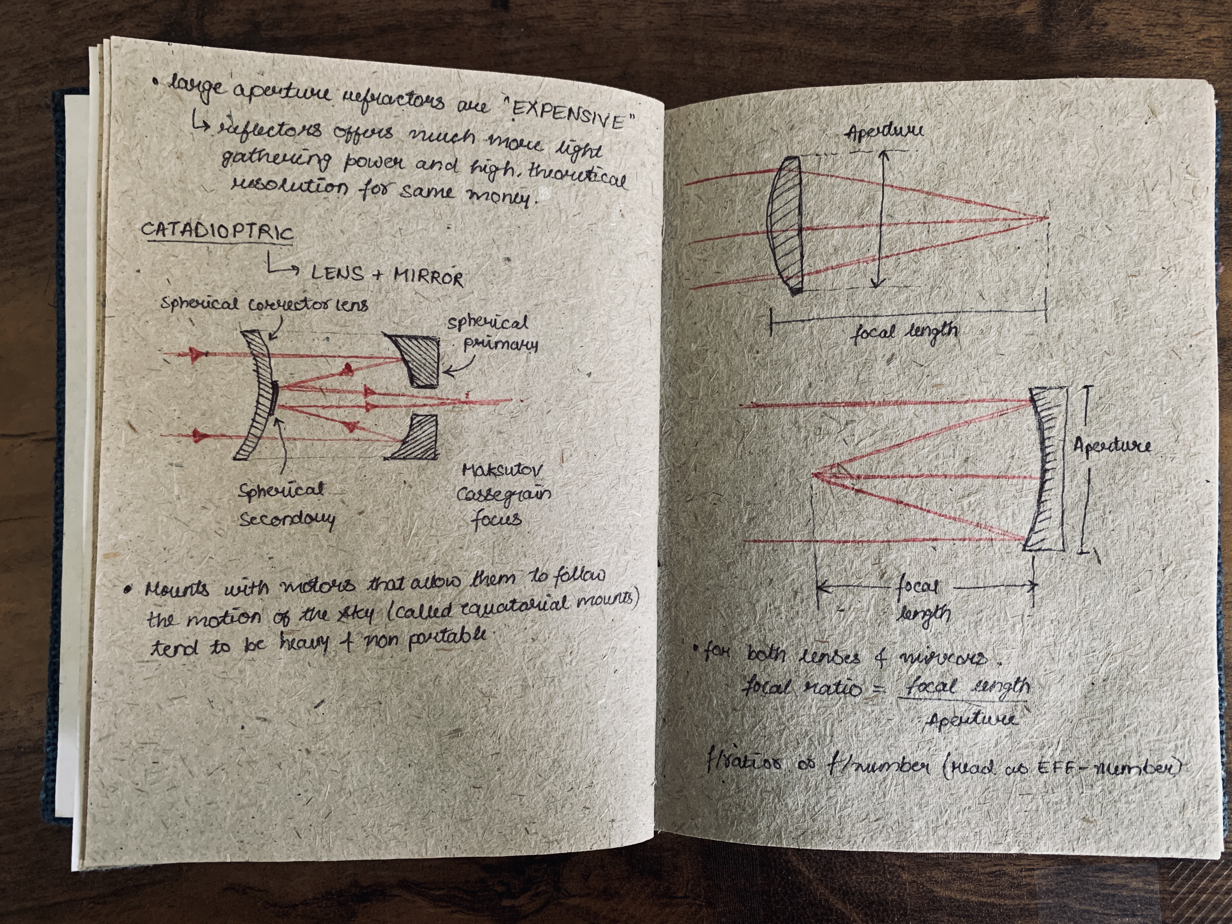
>> What is Focal Ratio & Magnification of a telescope?
$$FocalRatio = \frac{Focal Length}{Aperture} = \frac{900mm}{150mm} = 6$$
A focal ratio of 6 is an f/6 mirror
$$Magnification = \frac{FocalLengthTelescope}{FocalLengthEyepiece}$$
For a 25mm eyepiece
$$Magnification = \frac{900mm}{25mm} = 36$$
For a 9mm eyepiece
$$Magnification = \frac{900mm}{9mm} = 100$$
- Area of sky visible through an eyepiece = FIELD OF VIEW
- Area of sky covered is = REAL FIELD OF VIEW
- Angle you see when you look into the eyepiece = APPARENT FIELD OF VIEW
>> What is Diffraction & Airy Disk ?
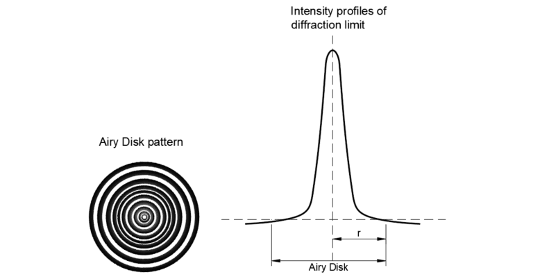
Diffraction: Bending of light near the edges of an obstacle similar to how water spreads out into waves when an obstruction is present in front of it. More on diffraction in telescope can be found >> Diffraction in Astronomy
Airy Disk: A very bright, circular spot of light formed in the center of image which together with the series of concentric rings around is called Airy Pattern.
To deep dive more ...
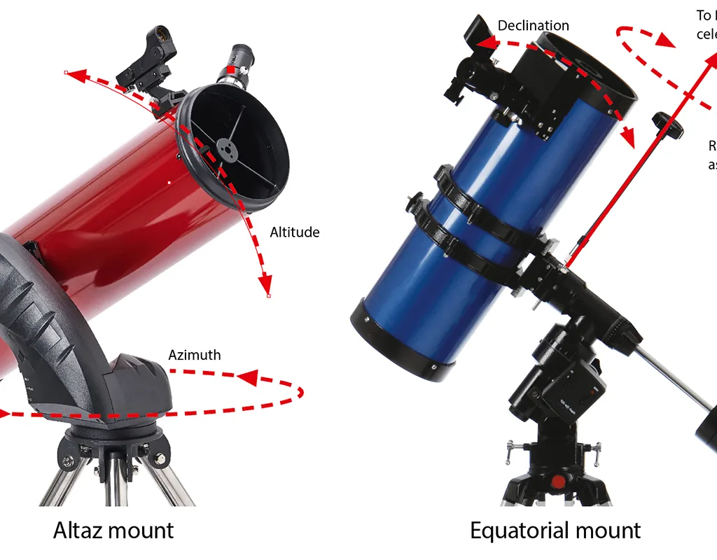
>> What is Dobsonian Mount & Equatorial Mount?
Dobsonian Mount
The first classic mount for any budding amateur astronomer that only requires screws, glue, plywood and that's it.
The name coming from a renowned amateur astronomer "John Dobson" is best known for promoting awareness regarding astronomy to the common people and thus guiding everyone with low cost & quick mount newtonian reflector telescope.
>> Telescope Building with John Dobson, a must watch video series on building a dobsonian mount.
Equatorial Mount
When you don't want to move your telescope manually, you opt for an equatorial mount which is designed to follow the track the movement of the objects in the night sky. Comparing with a dobsonian mount, equatorial mount offers more sturdy and expensive mount.
The motorized tracking of equatorial mount whose axis align with the earth's rotational axis. The electronics involved gives the opportunity to the user to play around with the overall navigation of the deep sky objects.